Amprobe ACD-23SW 사용자 설명서 - 페이지 12
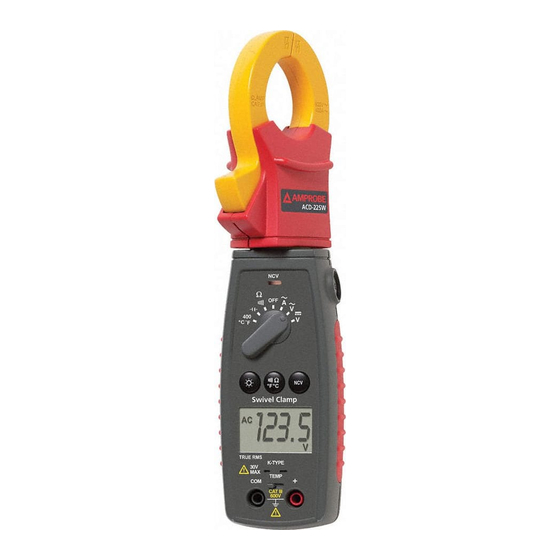
{카테고리_이름} Amprobe ACD-23SW에 대한 사용자 설명서을 온라인으로 검색하거나 PDF를 다운로드하세요. Amprobe ACD-23SW 20 페이지. Digital clamp meter
Continuity Testing
1. Set the Function Selector knob Switch to R (ACD-22SW) or "e / R " to
select the continuity test. Use the Auxiliary features push button (°F/°C/
R/e) to select continuity (ACD-23SW)
2. Connect the test leads: Red to +, Black to COM.
3. Turn off power to the circuit being measured.
4. Discharge any capacitors that may influence the reading.
5. Connect the test probes across the resistance or the two points of test
6. Listen for the tone that indicates continuity (< 25e).
Diode Testing (ACD-22SW)
1. Set the Function Swith to " " position.
2. Connect the red test lead to the "Ve" jack and the black test lead to the
"COM" jack.
3. Turn off power to the circuit under test. External voltage across the
components may cause invalid readings.
4. Connect the probes to the diode. A forward-voltage drop is about 0.6V
(typical for a silicon diode).
5. Reverse probes connection with the diode. If the diode is good, "OL"
isdisplayed. If the diode is shorted, "0.00" or another number is displayed.
6. If the diode is open, "OL" is displayed in both directions.
7. Audible Indication: Less than 0.25e.
Temperature Measurement (ACD-23SW only)
1. Verify that the location being tested is not electrically energized.
2. Set the Function Switch to 400°C°F position.
3. Move the slide knob to the TEMP position. Insert the thermocouple plug
matching the slot widths.
4. Connect the thermocouple bead to the test point. Refer to Fig.6
5. Read the display. If OL appears on the display, the temperature is too large
to be measured or the thermocouple is open.
6. Use the Auxiliary feature (°F/°C/R/e) push button to select ˚C or ˚F.
Note: The test leads must be removed to move the slide plate to allow the
thermocouple to be inserted.
7