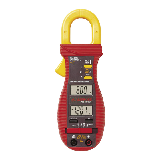
Amprobe ACD-14 TRMS-PLUS 사용 설명서 - 페이지 7
{카테고리_이름} Amprobe ACD-14 TRMS-PLUS에 대한 사용 설명서을 온라인으로 검색하거나 PDF를 다운로드하세요. Amprobe ACD-14 TRMS-PLUS 16 페이지. Tech clamp

Ω Resistance, and
Inputs are made through the test leads terminals. Move the slide-switch to the "Ω"
position. The unit defaults at Ω. Press SELECT button momentarily to select
Continuity function, which is convenient for checking wiring connections and operation
of switches. A continuous beep tone indicates a complete wire.
Diode test function
Inputs are made through the test lead terminals. Move the slide-switch to the "Ω"
position. The unit defaults at Ω. Press SELECT button momentarily 2 times to select
Diode test function.
Normal forward voltage drop (forward biased) for a good silicon diode is between
0.400V to 0.900V. A reading higher than that indicates a leaky diode (defective). A zero
reading indicates a shorted diode (defective).
An OL indicates an open diode (defective). Reverse the test leads connections
(reverse biased) across the diode. The digital display shows OL if the diode is good.
Any other readings indicate the diode is resistive or shorted (defective).
Capacitance function
Inputs are made through the test leads terminals. Move the slide-switch to the "Ω"
position. The unit defaults at Ω. Press SELECT button momentarily 3 times to select
Capacitance function.
CAUTION
Discharge capacitors before making any measurement. Large value capacitors should
be discharged through an appropriate resistance load.
Continuity functions
6
