DPCAV AV681TX 조립 지침 매뉴얼 - 페이지 2
{카테고리_이름} DPCAV AV681TX에 대한 조립 지침 매뉴얼을 온라인으로 검색하거나 PDF를 다운로드하세요. DPCAV AV681TX 8 페이지. 5.8ghz a/v transmitter kit
DPCAV AV681TX에 대해서도 마찬가지입니다: 빠른 시작 매뉴얼 (8 페이지)
1
GENERAL NOTES
1.1
These instructions are for the Rev-B hardware release. Before starting, be sure
to confirm your kit is a Rev-B.
1.2
The top and bottom sides of the two PCB's are labeled with a circled number
â ã ä å
(e.g.,
assembled.
ã ã ã ã ,
2
SIDE
COMPONENTS: See Figure 2.
9
2.1
Install C20 and C22 (47uF/6V caps).
9
2.2
Install C21 (47uF/16V cap).
9
2.3
Install D20 (diode).
9
2.4
Install U20 and U21 (Vreg IC).
Figure 3, Side
AV681TX-Kit, Rev B
ASSEMBLY INSTRUCTIONS
). The instructions will reference the numbered side that is being
3
SIDE
9
3.1
9
3.2
9
3.3
9
3.4
9
3.5
ä
ä ä ä ä ,
COMPONENTS: See Figure 3.
Install C1 and C3 (.1uF caps).
Install C6 and C7 (47uF/6V caps).
Install C2, C4, and C5 (330uF caps).
Install L1 (inductor).
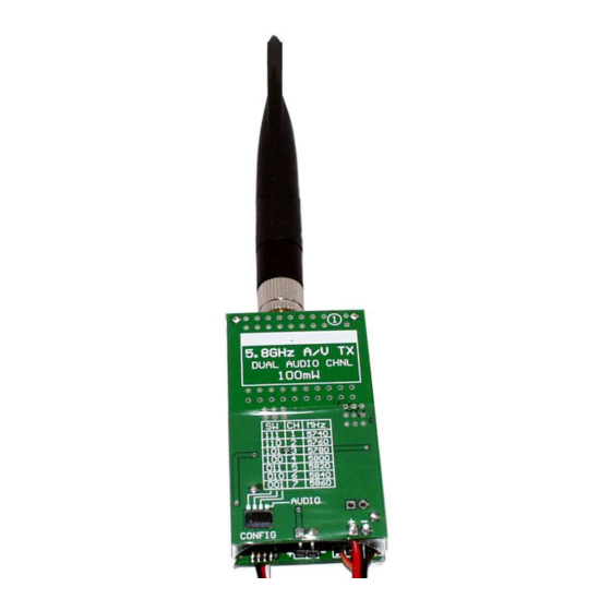
Install S1 (4-position switch). Orient it so that the
"1234" text is at the front edge.
Page 2
ã
Figure 2, Side
© Nov-03-2008