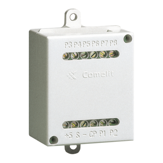
Comelit 1622 기술 매뉴얼 - 페이지 2
{카테고리_이름} Comelit 1622에 대한 기술 매뉴얼을 온라인으로 검색하거나 PDF를 다운로드하세요. Comelit 1622 20 페이지. Button interface
Comelit 1622에 대해서도 마찬가지입니다: 기술 매뉴얼 (20 페이지), 기술 매뉴얼 (20 페이지), 기술 지침 (14 페이지), 기술 매뉴얼 (8 페이지), 기술 매뉴얼 (6 페이지)

Warning
• Install the equipment by carefully following the instructions given by the manufacturer and in compliance with the
standards in force. Do not tamper with the internal elements offering protection against short circuits and overcurrents.
• All the equipment must only be used for the purpose it was designed for. Comelit Group S.p.A. declines any
responsibility for improper use of the apparatus, for any alterations made by others for any reason or for the use of
non-original accessories or materials.
• All the products comply with the requirements of the 2014/30/EU and 2014/35/EU directives. This is proved by the
CE mark on the products themselves.
• Do not route the riser wires in proximity to power supply cables (230/400V).
• Installation, mounting and assistance procedures for electrical devices must only be performed by specialised
electricians.
• Disconnect the power supply before carrying out any maintenance procedures.
• Connect the module support frame to earth (see Fig.)
Table of contents
Warning ............................................................................................ 2
Description ....................................................................................... 3
Installation information ................................................................... 4
Installation with Ikall external unit ................................................. 5
Installation with Vandalcom (A) Roma (B) external unit ............... 6
Vandalcom (A) ...........................................................................................6
Roma (B) ...................................................................................................6
Button programming ....................................................................... 7
Dip switch programming table ....................................................... 8
EXAMPLE: dip switch setting for code 200 ...........................................9
Special programming .................................................................... 10
Special programming table ...................................................................11
Operating distances with Art. 1595 .............................................. 13
Operating distances ...............................................................................13
Maximum system expansion .................................................................13
Wiring diagrams............................................................................. 14
voltage check with system in standby. ................................................14
Door-entry phone system with 2 audio ports, Ikall series .................15
Wiring diagram with safety lock ...........................................................16
Door open indication use variant..........................................................17
Protection device connection variant for line Art. 1237 .....................18
Use of RC network for lock filter on relay contacts ...........................18
2
