Comelit 1404 기술 매뉴얼 - 페이지 5
{카테고리_이름} Comelit 1404에 대한 기술 매뉴얼을 온라인으로 검색하거나 PDF를 다운로드하세요. Comelit 1404 18 페이지. Digital switching device for simplebus 2 system
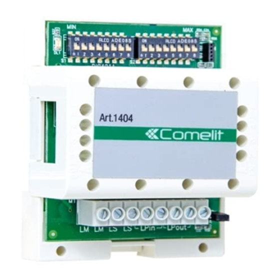
Operation and Programming
Switching device Art. 1404 includes 3 operating modes; the mode should be selected based on the type and position of the
switching device in that same system:
STANDARD (for use in systems which require the addition of extra external units)
TOP 1 (single zone switching in systems with no switchboard or with only one switchboard)
TOP 3 (multi-zone switching)
Standard mode (default)
To set STANDARD mode:
1. Set DIP1 and DIP2 of S3 to OFF.
2. Define the range of codes managed by each riser
S1 defines the minimum value MIN of the range (see table
S2 defines the maximum value MAX of the range (see table
CAUTION! Separate switching devices must manage code ranges which are not overlapping.
TOP 1 mode
To set TOP 1 mode:
1. Position the S3 DIP-switches as follows: DIP1-ON and DIP2-OFF.
2. Define the system area (called ZONE), using S1 and DIP3 of S3:
S1 defines the address (see table
The address is a number between 1 and 500 inclusive, and cannot be a range.
DIP3 of S3 defines the zone addresses managed:
•
OFF for zone addresses from 1 to 250 (default)
•
ON for zone addresses from 251 to 500
The LM-LM output of each switching device can be wired (as for a normal Simplebus system) with up to 240 users and
accessories (Art. 1256, Art. 1409); NOT the porter switchboard Art. 1998NA or Art. 1998NV.
The LS-LS input of the switching device can be wired with external units in STANDARD mode and accessories (Art. 1256, Art.
1409).
On the LPin-LPin input, the external units wired directly or indirectly via mixer art. 4888C must be set to TOP mode. A single
switchboard Art. 1998NA or Art. 1998NV can be installed in SERIES or PARALLEL (see corresponding manual).
All switchboard calls from door-entry phones or door entry monitors are addressed to the single switchboard in the system.
Self activation CANNOT be managed via wired external units on the LPin-LPin input of switching device Art. 1404.
CAUTION! There cannot be 2 switching devices Art. 1404 with the same ZONE address in the same system.
TOP 3 mode
To set TOP 3 mode:
1. Position the S3 DIP-switches as follows: DIP1-OFF and DIP2-ON.
2. Define the range of ZONES managed by the switching device, via S1, S2 and DIP3 of S3:
S1 defines the minimum value MIN of the range (see table
S2 defines the maximum value MAX of the range (see table
"Programming table for dip-switches and S3
"Programming table for dip-switches and S3
"Programming table for dip-switches and S3
"Programming table for dip-switches and S3
setting").
"Programming table for dip-switches and S3
setting").
setting").
setting").
setting").