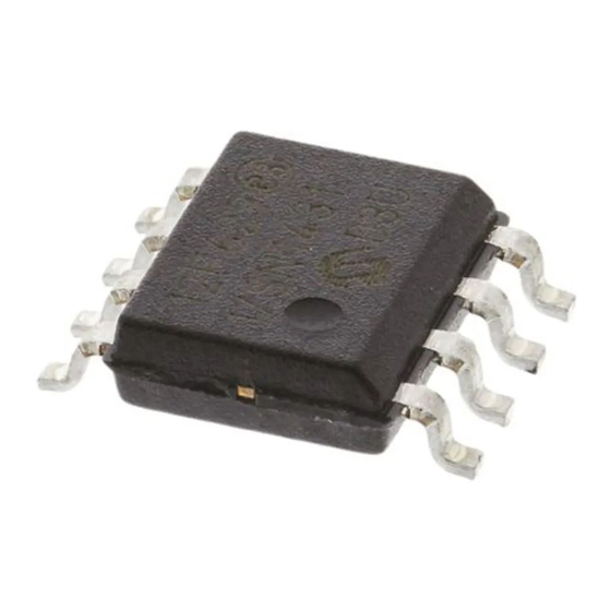
AMS AS5262 사용자 설명서 - 페이지 7
{카테고리_이름} AMS AS5262에 대한 사용자 설명서을 온라인으로 검색하거나 PDF를 다운로드하세요. AMS AS5262 11 페이지. Adapterboard, 12 bit magnetic angle position sensor with 2 outputs
AMS AS5262에 대해서도 마찬가지입니다: 프로그래밍 매뉴얼 (14 페이지)

AS5261/ AS5262 Adapterboard User manual
4. Operation case
Figure 5 Operation Case example pull up. This operation case is working for AS5261 as well.
The OUT pin (JP1 – 5) is used as output as well as programming interface. After the first power up,
the AS5261 or the AS5262 is in communication mode. During this mode different settings are
possible to program. via UART . After the fusing of the internal OTP ( one time programmable )
block, the AS5261 provides a pulse width modulated output (PWM) and the AS5262 provides an
analog output,
Figure 5 shows the recommended schematic for AS5261 and AS5262(pull up solution) in the
application. All components marked with (*) are optional and can be used to further increase the
EMC.For further information, please refer to datasheet.
5. Programming the AS5261 / AS5262
For programming of the AS5261 / AS5262 4 connections (VCC, GND and OUTTop, OutBottom)
or 6 connections (full redundant) are necessary. The AS5261 /AS5262 programming is a one-
time-programming (OTP) method, based on polysilicon fuses. The advantage of this method is
that no additional programming voltage is needed. The internal LDO provides the current for
programming.
The AS5261 / AS5262 uses a standard UART interface with an address byte and two data byte.
For programming the AS5261 / AS5262 there is a DemoSoftware ( Executable Labview) and an
easy UART-Interfaceboard available.
www.ams.com
Revision 1.0 / 10/31/12
page 6/10
