AMS AS5601 운영 매뉴얼 - 페이지 4
{카테고리_이름} AMS AS5601에 대한 운영 매뉴얼을 온라인으로 검색하거나 PDF를 다운로드하세요. AMS AS5601 12 페이지. Usb interface & programming box
AMS AS5601에 대해서도 마찬가지입니다: 사용자 설명서 (13 페이지), 매뉴얼 (13 페이지)

AS5601-SO_RD_ST
Operation Manual
Table 2:
Adapter Board Pin-Out (J1)
Pin
Symbol
Description
1
VDD
Positive Power Supply
2
PUSH
Output Pin
3
A
Output Pin
4
B
Output Pin
5
SDA
I2C Data
6
SCL
I2C Clock
7
GND
Ground
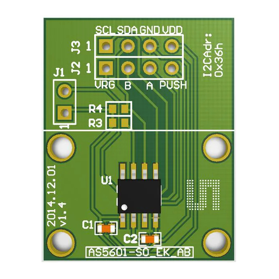
2.2 Adapter Board Description
The AS5601 is connected over the 7-way header. Connect the desired pins of the AS5601 using
the headers and resistors.
Figure 1:
AS5601-SO_RD_ST PCB Description
7-Way Header
2.3 Mechanical Setup
The contactless potentiometer reference design comes with the AS5601-SO_RD_ST PCB
assembled. The PCB holds all necessary components to operate the AS5601 in a contactless
potentiometer application with additional Pushbutton Detection.
The set-up of the module is shown below.
www.ams.com
Info
Contactless push-button output
Incremental output A
Incremental output B
Short J1
to operate
in 3.3V
mode
Revision 1.0 / 30.06.2014
page 4/11
