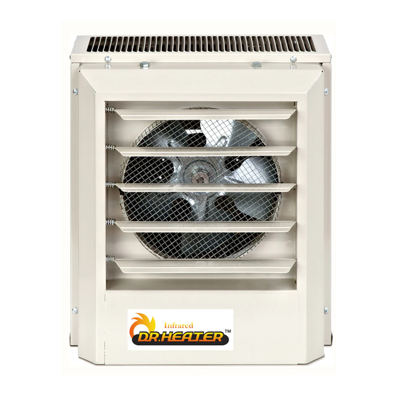
DR. Heater DR-P3150 소유자 매뉴얼 - 페이지 4
{카테고리_이름} DR. Heater DR-P3150에 대한 소유자 매뉴얼을 온라인으로 검색하거나 PDF를 다운로드하세요. DR. Heater DR-P3150 13 페이지. Heavy-duty electric unit heaters

All wiring must be installed by a certified electrician according to the electrical safety.
The ceiling heater must be grounded in accordance with all national and local building codes.
All wiring procedures and connections shall be in accordance with the national and local
codes having jurisdiction.
Before installation:
Disconnect the main supply connection.
The heater must be connected to individual branch circuit.
CAUTION:
High temperature, risk of fire, keep electrical cords, drapery, furnishings, and other
combustibles at least 3 feet (0.9 m) from the front of the heater and away from the side and rear.
WARNING:
To reduce the risk of fire, do not store or use gasoline or other flammable vapors and
liquids in the vicinity of the heater.
CAUTION :
Mount the heater at least 6
the fan blade which could cause injury.
CAUTION: To prevent possible over heating or damage due to overheating, keep at least a 5 feet
clearance in front of the heater. Refer to Table 1 for side, top and back clearance requirements.
Installation location:
1
Arrange units so their discharge air streams are subjected to a minimum of interference from
columns and partitions.
2 Direct air stream away from room occupants in comfort heating.
3 Air streams should wipe exposed wall without blowing directly at them.
4 Direct air stream along the windward side of a room when installed in a building exposed to a
prevailing wind.
5 If using a remote thermostat, locate thermostat approximately 5 feet above partition walls or posts
away from cold drafts, internal heat sources, and away from heater discharge air streams.
6 Large rooms require multi-unit installations. Arrange units to provide perimeter air circulation
where each unit supports the air stream from another.
Table 1 - Wall and Ceiling Clearance, inches(mm) / Mounting Brackets
Unit
3 & 5 kW
7.5 to 10 kW
15 to 20 kW
INSTALLING INSTRUCTIONS
Discharge
Horiz.
Vert.
Horiz.
Vert.
Horiz.
Vert
feet above the floor to prevent accidental contact with
Ceiling
2" (50.8)
6" (152.4)
6" (152.4)
6" (152.4)
6" (152.4)
6" (152.4)
Side Wall
6" (152.4)
18" (457.2)
6" (152.4)
24" (609.6)
9" (228.6)
12
24" (609.6)
Back Wall
9" (228.6)
18" (457.2)
13" (330.2)
24" (609.6)
1
/2" (317.5)
24" (609.6)
4
