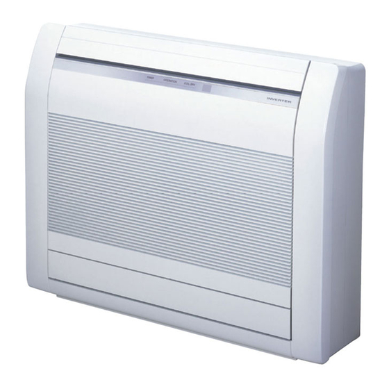
AirStage ABUA18TLAV 설치 매뉴얼 - 페이지 3
{카테고리_이름} AirStage ABUA18TLAV에 대한 설치 매뉴얼을 온라인으로 검색하거나 PDF를 다운로드하세요. AirStage ABUA18TLAV 17 페이지. Indoor unit

Request your dealer or a professional installer to install the indoor unit in accordance
with this Installation Manual. An improperly installed unit can cause serious accidents
such as water leakage, electric shock, or fi re. If the indoor unit is installed in disregard
of the instructions in the Installation Manual, it will void the manufacturer's warranty.
Do not turn ON the power until all work has been completed. Turning ON the power
before the work is completed can cause serious accidents such as electric shock or
fi re.
If refrigerant leaks while work is being carried out, ventilate the area. If the refrigerant
comes in contact with a fl ame, it produces a toxic gas.
Installation must be performed in accordance with the requirement of NEC(National
Electrical Code) and CEC(Canadian Electrical Code) by authorized personnel only.
Except for EMERGENCY, never turn off main as well as sub breaker of the indoor units
during operation. It will cause compressor failure as well as water leakage. First, stop
the indoor unit by operating the controller, converter or external input device and then
cut the breaker.
Make sure to operate through the controller, converter or external input device.
When the breaker is designed, locate it at a place where the users cannot start and
stop in the daily work.
2. ABOUT THIS PRODUCT
1
2.1. Precautions for using R410A refrigerant
Do not introduce any substance other than the prescribed refrigerant into the
refrigeration cycle. If air enters the refrigeration cycle, the pressure in the refrigeration
cycle will become abnormally high and cause the piping to rupture.
If there is a refrigerant leak, make sure that it does not exceed the concentration limit.
If a refrigerant leak exceeds the concentration limit, it can lead to accidents such as
oxygen starvation.
Do not touch refrigerant that has leaked from the refrigerant pipe connections or other
area. Touching the refrigerant directly can cause frostbite.
If a refrigerant leak occurs during operation, immediately vacate the premises and
thoroughly ventilate the area. If the refrigerant comes in contact with a flame, it
produces a toxic gas.
] 1
2.2. Special tool for R410A
To install a unit that uses R410A refrigerant, use dedicated tools and piping materials
that have been manufactured specifically for R410A use. Because the pressure
of R410A refrigerant is approximately 1.6 times higher than the R22, failure to
use dedicated piping material or improper installation can cause rupture or injury.
Furthermore, it can cause serious accidents such as water leakage, electric shock, or
fi re.
Tool name
The pressure in the refrigerant system is extremely high
and cannot be measured with a conventional gauge. To
prevent erroneous mixing of other refrigerants, the diameter
Gauge manifold
of each port has been changed. It is recommended to use
a gauge manifold with a high pressure display range of 30
in.Hg to 768 psi (–0.1 to 5.3 MPa) and a low pressure dis-
play range of 30 in.Hg to 551 psi (–0.1 to 3.8 MPa).
To increase pressure resistance, the hose material and
base size were changed.
Charging hose
(The charging port thread diameter for R410A is 1/2 UNF
20 threads per inch.)
A conventional vacuum pump can be used by installing a
vacuum pump adapter.
Vacuum pump
Be sure that the pump oil does not backfl ow into the sys-
tem. Use one capable for vacuum suction of 5 Torr, –755
mm Hg (–100.7 kPa).
Gas leakage detector
Special gas leakage detector for R410A refrigerant.
WARNING
WARNING
WARNING
Changes
] 1
2.3. Accessories
For installation purposes, be sure to use the parts supplied by the manufacturer or
other prescribed parts. The use of non-prescribed parts can cause serious accidents
such as the unit falling, water leakage, electric shock, or fi re.
The following installation parts are furnished. Use them as required.
Keep the Installation Manual in a safe place and do not discard any other accessories
until the installation work has been completed.
Name and Shape
Operating Manual
Installation Manual
Cover plate (Left)
Cover plate (Right)
Tapping screw
(M4 × 10mm)
Installation template
Bracket (Left)
Bracket (Right)
Special nut
Wall bracket
Tapping screw
(M4 × 20mm)
Coupler heat insulation
Cable tie (Large)
Cable tie (Medium)
Drain hose
Hose Band
WARNING
Q'ty
Application
1
(This book)
1
1
1
2
For positioning the indoor unit
1
For under ceiling type
For suspending the indoor unit from
ceiling
1
1
4
For suspending the indoor unit on the
wall
2
For fi xing the wall bracket
6
For indoor side pipe joint
2
For fi xing the coupler heat insulation
4
For power supply, transmission and
2
remote controller cable binding
For installing drain pipe
Ø 3/4 in. (19 mm) [I.D.],
1
Ø 1-1/16 in. (27 mm) [O.D.]
For installing drain hose
1
En-2
