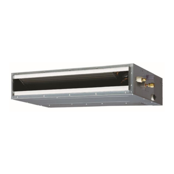
AirStage ARUL18RLAV 설치 매뉴얼 - 페이지 15
{카테고리_이름} AirStage ARUL18RLAV에 대한 설치 매뉴얼을 온라인으로 검색하거나 PDF를 다운로드하세요. AirStage ARUL18RLAV 20 페이지. Indoor unit (duct type)
AirStage ARUL18RLAV에 대해서도 마찬가지입니다: 운영 매뉴얼 (8 페이지)

DC power supply
12 to 24 V
Load
resistance
Load
resistance
Connected unit
• No voltage terminal ([CN17])
When a power supply is unnecessary at the input device you want to connect, use the no
voltage terminal ([CN17]).
*c
*c
Ch 2
Ch 1
Connected unit
*c Select very low current use contacts (usable at DC12V,
*d The wiring is different from voltage terminals. Be suffi ciently careful when wiring.
When connected to no voltage terminals of multiple indoor units with a connected unit,
insulate each indoor unit with relay, etc. as shown on below example.
When connected to multiple indoor units directly, it will cause breakdown.
K1
K2
K3
Input device 1
Input device 2
Operation behavior
• Input signal type
The input signal type can be selected.
It is switched by Dip-sw on the indoor
unit PCB.
Dip-sw [Set 2-2]
Input signal type
OFF
ON
• When function setting is "Start/Stop" mode
In the case of "Edge" input
Connector
Input signal
Ch1 of
CN6 or CN17
In the case of "Pulse" input
Connector
Ch1
CN6 or CN17
Ch2
* The last command has priority.
* The indoor units within the same remote controller group operates in the same mode.
P.C.B
CN6
P.C.B
CN6
P.C.B
CN6
P.C.B
1
CN17
2
3
GND
*d
DC1mA or less).
P.C.B
K4
CN17
P.C.B
K5
CN17
P.C.B
K6
CN17
K1-K6: Relay
Edge
Pulse
The width of pulse
must be longer than
Edge
200msec.
Pulse
Command
OFF → ON
Operation
ON → OFF
Stop
Input signal
Command
OFF → ON
Operation
OFF → ON
Stop
• When function setting is "Emergency stop" mode
In the case of "Edge" input
Connector
Input signal
Ch1 of
CN6 or CN17
In the case of "Pulse" input
Connector
Ch1
CN6 or CN17
Ch2
* All indoor units of same refrigerant system stops when Emergency stop operates.
• When function setting is "Forced stop" mode
In the case of "Edge" input
Connector
Input signal
Ch1 of
CN6 or CN17
In the case of "Pulse" input
Connector
Ch1
CN6 or CN17
Ch2
* When the forced stop is triggered, indoor unit stops and Start/Stop operation by a
remote controller is restricted.
* When forced stop function is used with forming a remote controller group, connect the
same equipment to each indoor unit within the group.
• Selection method of functions
"Start/Stop" mode or "Emergency stop" mode, "Forced stop" mode can be selected with
function setting of indoor unit.
(2) External output terminals
• When picking up output signals for operating status, abnormal conditions or indoor unit
status.
Wiring methods and specifi cations
DC power supply
12 to 24 V *2
Connected load
*3
Connected load
*3
Connected load
*3
Connected unit
*2 Provide a DC12 to 24V power supply. Select a power supply capacity
with an ample surplus for the connected load.
*3 The allowable current is 30mA or less. Provide a load resistance such
that the current becomes 30mA or less.
*4 Polarity is [+] for pin 1 and [-] for pins 2-4. Connect correctly.
Do not impress a voltage exceeding 24V across pins 1-2, 1-3, and 1-4.
Operation behavior
Connector
External output1
Pins 1-2
External output2
CN16
Pins 1-3
External output3
Pins 1-4
A twisted pair cable (22AWG) should be used. Maximum length of cable is 492 ft. (150 m).
* Use an external input and output cable with appropriate external dimension, depending
on the number of cables to be installed.
Command
OFF → ON
Emergency stop
ON → OFF
Normal
Input signal
Command
OFF → ON
Emergency stop
OFF → ON
Normal
Command
OFF → ON
Forced stop
ON → OFF
Normal
Input signal
Command
OFF → ON
Forced stop
OFF → ON
Normal
P.C.B
CN16
+
-
+
1
-
2
-
3
-
4
*4
Output voltage
Status
0V
Stop
DC 12 to 24 V *2
Operation
0V
Normal
DC 12 to 24 V *2
Error
0V
Indoor unit fan stop
DC 12 to 24 V *2
Indoor unit fan operation
En-14
