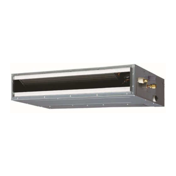
AirStage ARUL7RLAV 설치 매뉴얼 - 페이지 16
{카테고리_이름} AirStage ARUL7RLAV에 대한 설치 매뉴얼을 온라인으로 검색하거나 PDF를 다운로드하세요. AirStage ARUL7RLAV 20 페이지. Indoor unit (duct type)
AirStage ARUL7RLAV에 대해서도 마찬가지입니다: 운영 매뉴얼 (8 페이지)

(3) Connection methods
• Wire modifi cation
Remove insulation from wire attached to wire kit connector. Remove insulation from fi eld
supplied cable. Use crimp type insulated butt connector to join fi eld cable and wire kit wire.
Connect the wire with connecting wire with solder.
Important: Be sure to insulate the connection between the wires.
Insulated connection
Field supply
Controller PCB
Input No Voltage terminal (CN17)
Input Voltage terminal (CN6)
Controller PCB
En-15
Option parts
External input/output wire
Output terminal (CN16)
6.6. Remote sensor (Optional parts)
Connection method
• Connection terminals
Controller PCB
Remote sensor terminal (CN8)
• Wiring arrangement
Controller PCB
• Remove the existing connector and replace it with the remote sensor connector (ensure
that the correct connector is used).
• The original connector should be insulated to ensure that it does not come into contact
with other electrical circuitry.
• Use conduit hole when external output cable is used.
Setting for room temperature correction
When a remote sensor is connected, set the function setting of indoor unit as indicated
below.
• Set Function Number "30" (Cool air temperature trigger) to "00" (Default)
• Set Function Number "31" (Hot air temperature trigger) to "02" (Adjust(2))
Clamp
