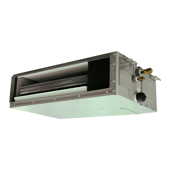
AirStage ARXD009GLEH 설치 매뉴얼 - 페이지 15
{카테고리_이름} AirStage ARXD009GLEH에 대한 설치 매뉴얼을 온라인으로 검색하거나 PDF를 다운로드하세요. AirStage ARXD009GLEH 18 페이지. Indoor unit (duct type)

NOTE :
When connected to multiple indoor units directly, it will cause breakdown.
Operation behavior
● Input signal type
The input signal type can be selected.
It is switched by DIP switch on the indoor unit PCB.
DIP switch [Set 2 SW2]
Input signal type
OFF (Factory setting)
Edge
ON
Pulse
● When function setting is "Operation/Stop" mode.
[In the case of "Edge" input]
Connector
Input signal
Ch1 of CNA01 or CNA02
[In the case of "Pulse" input]
Connector
Input signal
Ch1
CNA01 or CNA02
Ch2
* The last command has priority.
* The indoor units within the same remote controller group operates in the same mode.
● When function setting is "Emergency stop" mode.
[In the case of "Edge" input]
Connector
Input signal
Ch1 of CNA01 or CNA02
[In the case of "Pulse" input]
Connector
Input signal
Ch1
CNA01 or CNA02
Ch2
* All indoor units of same refrigerant system stops when Emergency stop operates.
● When function setting is "Forced stop" mode.
[In the case of "Edge" input]
Connector
Input signal
Ch1 of CNA01 or CNA02
[In the case of "Pulse" input]
Connector
Ch1
CNA01 or CNA02
Ch2
* When the forced stop is triggered, indoor unit stops and Operation/Stop operation by a
remote controller is restricted.
* When forced stop function is used with forming a remote controller group, connect the
same equipment to each indoor unit within the group.
• Selection method of functions
"Operation/Stop" mode or "Emergency stop" mode, "Forced stop" mode can be selected
with function setting of indoor unit.
● Forced thermostat off function
["Edge" input only]
Function
Connector
setting
Ch3 of CNA03 or
60-00
CNA04
● Refrigerant leak detection function (only for J-IIIL series)
["Edge" input only]
Function
Connector
setting
Ch3 of CNA03 or
60-09
CNA04
Edge
Pulse
The width of pulse
must be longer than
200msec.
Command
OFF → ON
Operation
ON → OFF
Stop
Command
OFF → ON
Operation
OFF → ON
Stop
Command
OFF → ON
Emergency stop
ON → OFF
Normal
Command
OFF → ON
Emergency stop
OFF → ON
Normal
Command
OFF → ON
Forced stop
ON → OFF
Normal
Input signal
Command
OFF → ON
Forced stop
OFF → ON
Normal
Input signal
Command
OFF → ON
Thermostat off
ON → OFF
Normal
Input signal
Command
OFF → ON
No command
ON → OFF
Refrigerant leak
(2) External output
• A twisted pair cable (22AWG) should be used. Maximum length of cable is 25m.
• Use an external input and output cable with appropriate external dimension, depending
on the number of cables to be installed.
• Output voltage: Hi DC12V±2V, Lo 0V.
• Permissible current: 50mA
Output select
● When indicator etc. are connected directly
Operation
indicator
Error
indicator
Indoor unit Fan
status indicator
connected unit
● When connecting with unit equipped with a power supply
Connected
device 1
Connected
device 2
Connected
device 3
connected unit
Relay (locally purchased)
Operation behavior
Connector
External output1
Pins 1-2
External output2
CNB01
Pins 1-3
External output3
Pins 1-4
6.7. Remote sensor (Optional parts)
Connection method
• Remove the existing connector and replace it with the remote sensor connector (ensure
that the correct connector is used).
• The original connector should be insulated to ensure that it does not come into contact
with other electrical circuitry.
• Use conduit hole when external output cable is used.
Setting for room temperature correction
When a remote sensor is connected, set the function setting of indoor unit as indicated
below.
• Function Number "30":
Set the Setting Number to "00". (Default)
• Function Number "31":
Set the Setting Number to "02".
* Refer to "7.6. Function setting" for details about Function Number and Setting Number
6.8. IR receiver unit (Optional parts)
• For the installation method, please refer to the INSTALLATION MANUAL of IR receiver
unit.
Connection method
• Use 9 pins for receiver unit cable.
• At fi rst, connect the receiver unit cable to the controller PCB.
• Attach the core that comes between controller PCB and the clamp.
• Use conduit hole when external output cable is used.
6.9. Auto louver grille kit (Optional parts)
• For the installation method, please refer to the INSTALLATION MANUAL of Auto louver
grille kit.
P.C.B
P.C.B
Output voltage
Status
0V
Stop
DC 12 V
Operation
0V
Normal
DC 12 V
Error
0V
Indoor unit fan stop
DC 12 V
Indoor unit fan operation
CNB
01
CNB
01
En-14
