DRAKE DQT1000 사용 설명서 - 페이지 12
{카테고리_이름} DRAKE DQT1000에 대한 사용 설명서을 온라인으로 검색하거나 PDF를 다운로드하세요. DRAKE DQT1000 15 페이지. Digital to qam transcoder; multiplexing qam modulator

12
Operation / Additional Information
OPERATION - MULTIPLEXING TWO ATSC INPUTS
To use the DQT1000 or the MQM1000 to multiplex two
ATSC inputs, proceed as follows:
1) Connect the off-air antenna or CATV feed to the
DEMOD A and DEMOD B inputs of the DQT1000 or
connect the two ASI inputs to the MQM1000. For the
DQT1000 the two input connectors are separate in
case the two RF signals must come from different
antennas or if one signal is coming from a cable
system, etc. If using a common antenna, use a good
quality two way splitter to split the antenna and feed
each input.
2) Plug the power cord from the unit into the power
source.
3) Follow the instructions in the programming section
above to set the channel map and channel number for
both DEMOD A and DEMOD B - DQT1000 only.
4) Set the DEMOD SYMRATE to PRESET for both the A
and B channel - DQT1000 only.
5) Set the MULTIPLEX setting to DEMOD B for the
DQT1000 or to ASI for the MQM1000
6) Set the MUX OFFSET to 10. Read details in pro-
gramming section to determine if you need another
value.
7) Select the desired MPEG programs. (See the
previous section for details.)
8) In the PSIP menu, select BASIC MGT VCT for now,
this may be changed later. See programming section
for detail.
9) In the VCT TABLE menu, select TVCT.
10) In the MAJOR CHANNEL menu, select OUTPUT
CHANNEL. This may be changed later.
11) From the QAM MODE menu, set the QAM modulator
to QAM-256B for use in a DigiCipher II environment. If
DVB, use QAM-256A instead.
12) In the QAM SYMRATE menu, select PRESET.
13) Set the INTERLEAVER to I128,J1 if in a DigiCipher
II environment. There is no interleaver menu when the
QAM mode is set to A (DVB).
14) Set the OUTPUT FORMAT to NORMAL.
15) Set the OUTPUT CHANMAP and OUTPUT CHAN-
NEL to the desired EIA CATV output channel.
If the second program is being input to a DQT1000 via the
ASI input instead of DEMOD B, the same steps apply
except that the MULTIPLEX setting will be ASI and there
will be no parameters to set for DEMOD B.
SET TOP BOX MAPPING
When setting up a program map for your set top boxes to
include off-air channels that are multiplexed by the
DQT1000 or MQM1000 be sure to inform the programmer
that the MPEG program numbers for the programs coming
in through DEMOD B or ASI B have been offset by the
amount selected in the MUX OFFSET menu. As an
example: If input A is providing a channel with MPEG
programs 1 and 2 in the stream and input B is providing a
channel with MPEG programs 1, 2, 3, 4, and 5 in the
stream, and the MUX OFFSET is set to 10, then the new
output signal will contain MPEG programs with program
numbers of 1, 2, 11, 12, 13, 14, and 15. If the set top is not
looking for the right program number, you will not receive
any video!
ADDITIONAL INFORMATION
STANDBY MODE
The DQT1000 and MQM1000 have a standby output mode
which turns off the RF output. This can be used when it is
desirable to temporarily disable the output without
unplugging the AC line cord. Select STANDBY in the
OUTPUT FORMAT menu.
EAS
The DQT1000 and MQM1000 provide an IF input for
Emergency Alert System applications. See R2 in the rear
panel connections descriptions.
OVER TEMPERATURE SENSOR
Temperature monitoring is built into these products. If the
ventilation holes or fan output opening are blocked or the
fan should stop, overheating can occur. If this condition is
detected, the default LCD message will change to OVER
TEMP. If this occurs, the problem should be corrected as
soon as possible. The unit will remain operational but the
ventilation must be restored to prevent premature part
failures due to overheating.
STATUS DISPLAYS
When the units are not in the adjust/program mode, status
displays are shown. These vary by model: DQT1000 -
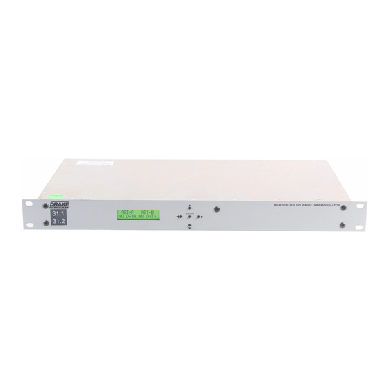
shows DEMOD A and DEMOD B SNRs. MQM1000 shows
ASI A and ASI B data presence. QQP860 - shows demod
SNR and ERRORS. The ERRORS display is a five digit
number that shows the number of correctable errors that
were processed in a 4.5 second window. A low number is
best.
Pushing the UP arrow button will cause the firmware
version number to display. Pressing the DOWN arrow will
cause QAMSYMRATE to display - the output symbol rate of
the QAM modulator.
REMOTE CONTROL AND MONITORING
The DQT1000 or MQM1000 may be used with the 'Drake
Digital Headend Remote Control Software' program to
allow remote monitoring or control. Only version 2.6 or
newer are compatible with the DQT1000 or MQM1000.
Connect the RS232 cable coming from the PC or modem
to the RS232 IN DB9 rear panel connector.
Assign a UNIT ID (1 to 63) to use the remote program.
Leave at, or set to, 0 if no remote access is desired.
Set the RS232 BAUD RATE to match the PC setting.
If you are familiar with the program, operation will be clear.
If not familiar with it, see further instructions in the insert
provided with the CDROM or stored on the CDROM.
OPTIONS
A second RF demodulator module, PN 1002369, may be
added by the Drake service department to a DQT1000 that
was initially purchased with only one RF input.
A DVB ASI input board, PN 1002368, is available for
installation into a DQT1000.
