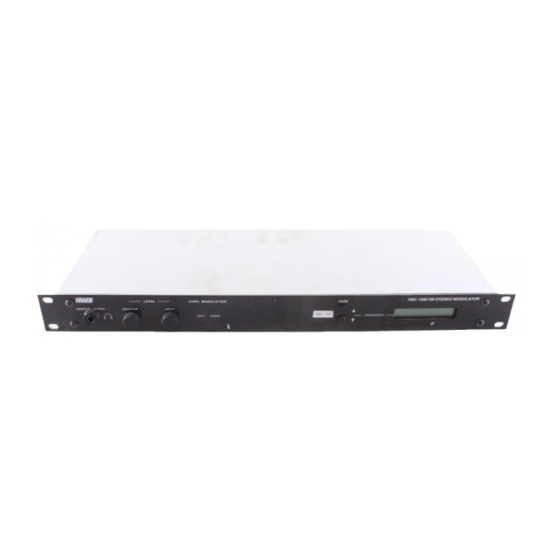
DRAKE FMC 1000 사용 설명서 - 페이지 10
{카테고리_이름} DRAKE FMC 1000에 대한 사용 설명서을 온라인으로 검색하거나 PDF를 다운로드하세요. DRAKE FMC 1000 14 페이지. Fm stereo modulator

4
Installation
SETUP and OPERATION
Rack Mounting
Adequate ventilation is very important in multichannel
installations. Units should be spaced apart by at least
one panel height wherever possible. Some air
movement is advisable in enclosed rack cabinets.
Excessive heat will shorten component life and
modulator performance will be degraded without
proper cooling.
Installation Notes
Level adjustment provides optimum performance in
multichannel installations. The RF output level from the
FMC 1000 is +50 dBmV nominal. The level can be
reduced to a value approximately 10 dB below the
nominal level by adjustment of the potentiometer that is
tunable through the rear panel access hole. The
access hole is located adjacent to the RF OUTPUT
connector. Use a small straight-slot type screwdriver to
adjust the potentiometer, if adjustment is necessary.
Counterclockwise rotation of the potentiometer
decreases the RF output level. If an output level of less
M A D E I N U . S . A .
BY
R
D C I N P U T
R F O U T P U T
P O W E R
O N
O F F
+
--
1 2 V D C
2 5 0 m A
To Combiner/Cable Distribution
Balanced
Line
Unbalanced
Line
L I M I T I N G /
C O M P R E S S I O N
O F F
C + L
L
Access hole for RF output level
potentiometer
Shield Grounded As Required
than +40 dBmV is required, add an attenuator of the
appropriate value to the modulator output.
Example: For an output level of +35 dBmV, add a 10 dB
attenuator pad to the modulator output and adjust the
level.
1. Connect the RF Output coaxial cable to the RF
OUTPUT connector.
2. Make audio connections
The FMC 1000 will accept line level audio inputs. The
best sources for a signal from a sound system are as
follows:
A. TAPE OUT or LINE OUT
B. BOOSTER or BRIDGING
C. Speaker Terminal
Use XLR connectors to connect balanced audio
signals to the FMC 1000 AUDIO INPUTs. Use RCA
phono connectors to connect unbalanced audio
signals to the FMC 1000 AUDIO INPUTs. The following
diagrams illustrate balanced and unbalanced audio
wiring details:
L E F T A U D I O
I N P U T
( M O N O )
G R O U N D
2 0 K
2 0 K
U N B A L A N C E D
B A L A N C E D
+
--
--
+
1 6 T O
4 d B u
1 0 T O
1 0 d B u
Male XLR Connector To
FMC 1000 Input
-
2
1
+
3
RCA Phono Connector
To FMC 1000 Input
--
1
G N D
R I G H T A U D I O
--
2
H I G H
--
I N P U T
3
L O W
L I F T
2 0 K
2 0 K
B A L A N C E D
U N B A L A N C E D
O N
O F F
+
--
+
--
1 0 T O
1 0 d B u
1 6 T O
4 d B u
OR
