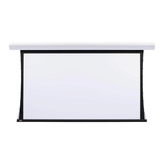
Draper Silhouette E Series 설치 및 운영 지침 - 페이지 2
{카테고리_이름} Draper Silhouette E Series에 대한 설치 및 운영 지침을 온라인으로 검색하거나 PDF를 다운로드하세요. Draper Silhouette E Series 4 페이지. Electric projection screen
Draper Silhouette E Series에 대해서도 마찬가지입니다: 설치 및 운영 지침 (5 페이지)

Silhouette/Series E & V by Draper
To mount suspended from ceiling, the brackets need to be installed on
screen case as noted on page 1. Attach "S" Hooks (supplied) through the
holes in the brackets. Select the set of holes that allows the screen to hang
in a vertical position. The installer is to provide the materials and fasteners
to attach the "S" Hooks to the ceiling. Installer must insure that the fasteners
and suspension material is of adequate strength and suitable for the
mounting surface chosen.
Mounting on 6" extension wall brackets: Special 6" extension brackets
are needed to mount Silhouette extended from wall. Brackets are not
supplied with screen and must be ordered separately. Specify "Silhouette
Extension Brackets".
Attach right angle adapter to top of extension bracket as shown using (1)
pan head screw and (1) locking nut. Attach (1) "Z" Clip wall mounting
bracket (supplied with screen) to front of extension bracket as shown using
(1) pan head screw and (1) locking nut. (Make sure "Z" Clip is oriented 90°
to angle adapter.)
Wall mount the extension brackets to wall, making sure they are level and
vertically plumb. Installer must insure fasteners are of adequate strength
and suitable for chosen mounting surface. Back out the top stop screw until
it is flush with front side of angle adapter.
Engage the lip on back of screen case with lip of "Z" Clip and gently pull
down to fully engage case to brackets. Screw in stop screw on each bracket
to lock screen case in place.
Angle adapter
Wall bracket
Extension Arm
Front view of assembled
extension bracket
Removing Case Fascia
Case fascia is removable to access roller assembly. To remove fascia,
depress outward the spring lip located inside lower front corner of screen
case and pull lower corner of fascia outward. Repeat this at right end of
case. Support fascia from center and rotate lower front edge upward
approximately 40° to disengage the Roll-Lok hinge at the top front of
screen case. Fascia can now be completely removed from case.
To install fascia, generally reverse instructions above making sure the Roll-
Lok hinge is completely engaged before rotating fascia down towards the
closed position. Depress spring clips outward, push lower corners of fascia
inward until lips of spring clips hook behind fascia.
Locking screw
Wall bracket*
Angle adapter*
Extension
bracket
*Supplied with screen
90˚
Electrical Connections
Screen operates on 110-120v, 60 Hz. current.
Junction box is located at left end of screen. It is accessible through front of
screen case after fascia is removed. (See instructions above for removing
fascia.)
Electrical supply wires can enter through the back or top of case. For top
entry, remove plug from top conduit hole and snap plug into hole on back
side of case.
Junction box contains red, black, and white pigtail leads and green internal
ground wire per wiring diagram attached.
If optional low voltage control or video interface control is specified and
factory installed, please refer to wiring diagram on page 3.
Wall or ceiling electrical box should be installed so as to be fully concealed
by screen case after installation.
Screen is shipped with internal wiring complete and control switch(es) fully
boxed. Wire to connect screen to switch(es) and switch(es) to power supply
should be furnished by installer. Connections should be made in accor-
dance with attached wiring diagram, and wiring should comply with national
and local electrical codes.
All operating switches should be "off" before power is connected.
Operation
Before operating screen, remove any shipping brackets or tape securing
fabric and dowel to the roller. If viewing surface hangs out of case 8" or 9",
tape has probable been broken by rough handling in shipment, allowing
surface to "unwrap" one turn off the roller. Manually wrap fabric back around
the roller without turning the roller itself.
When screen is first operated, be cautious! Cycle unit down and up several
times to confirm satisfactory operation.
110-120v SINGLE STATION CONTROL—3-position UP-OFF-DOWN switch
permits operation to be stopped at any point. Factory adjusted limit switches
automatically stop screen when fully down or fully up.
110-120v MULTIPLE STATION CONTROL—Switches are similar in
appearance to 110-120v Single Station Control. Screen stops when switch
is released and may be restarted in either direction. Factory adjusted limit
switches stop screen automatically when fully up or fully down.
24v MULTIPLE STATION CONTROL—Three-button UP-STOP-DOWN
switches stop at any point desired, operate in any sequence. Factory
adjusted limit switches automatically stop screen when fully up or fully
down.
110-120v & 12v VIDEO INTERFACE CONTROL—Allows screen to be
controlled by a trigger signal—when the signal comes on, the screen
descends automatically. Two versions: Model VIC115 integrates screen
operation with a DRAPER video projector lift or a video projector or tuner
with a 110-120v switch outlet. Model VIC12 interfaces with a 12V switch
outlet. Both available with an override switch (VIC–OS), permitting
independent operation. VIC–OS not available with factory installed VIC115
& VIC12.
KEY OPERATED SWITCHING—Two kinds of key-operated switches are
optionally available with this unit.
➀ The key-operated power supply switch controls power to the screen and
switches. When it is "off", the switches will not operate screen.
Key may be removed from the switch in either "on" or "off" position.
➁ A three-position key switch permits the screen to be operated directly by
key. In this case, the screen's operator must always have a key.
Page 2 of 4
