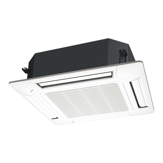
AirStage AUUB24TLAV 설치 매뉴얼 - 페이지 4
{카테고리_이름} AirStage AUUB24TLAV에 대한 설치 매뉴얼을 온라인으로 검색하거나 PDF를 다운로드하세요. AirStage AUUB24TLAV 17 페이지. Indoor unit (cassette type)

Do not use the unit for special purposes, such as storing food, raising animals,
growing plants, or preserving precision devices or art objects.
It can degrade the quality of the preserved or stored objects.
Do not install where there is the danger of combustible gas leakage.
Do not install the unit near a source of heat, steam, or fl ammable gas.
Install the unit where drainage does not cause any trouble.
Install the indoor unit, power supply cable, transmission cable, and remote controller
cable at least 40 in. (1 m) away from a television or radio receivers. The purpose of
this is to prevent TV reception interference or radio noise.
(Even if they are installed more than 40 in. (1 m) apart, you could still receive noise
under some signal conditions.)
If children under 10 years old may approach the unit, take preventive measures so
that they cannot reach the unit.
Decide the mounting position with the customer as follows:
(1) Install the indoor unit on a place having a suffi cient strength so that it withstands
against the weight of the indoor unit.
(2) The inlet and outlet ports should not be obstructed; the air should be able to blow all
over the room.
(3) Leave the space required to service the air conditioner.
(4) A place from where the air can be distributed evenly throughout the room by the unit.
(5) Install the unit where connection to the outdoor unit (or RB unit) is easy.
(6) Install the unit where the connection pipe can be easily installed.
(7) Install the unit where the drain pipe can be easily installed.
(8) Install the unit where noise and vibrations are not amplifi ed.
(9) Take servicing, etc., into consideration and leave the spaces. Also install the unit
where the fi lter can be removed.
3.2. Installation dimensions
Ceiling height is as shown in the fi gure.
11 in. (256 mm) or more (AUUB 18/24)
12 in. (298 mm) or more (AUUB 30/36)
Strong and durable ceiling
119 in. (3,000 mm) or more
71 in. (1,800 mm) to H
40 in. (1,000 mm) or more
H: Maximum height from fl oor to ceiling
Function setting
AUUB18
Standard mode
118 (3,000)
High Ceiling mode
137 (3,500)
* Be sure to make the function settings with the remote controller according to the
installed ceiling height.
Discharge Direction Setting
• The discharge direction can be selected as shown below.
4 DIRECTION
* Select the most appropriate airfl ow direction from 3 or 4 directions according to the
shape of the room and the installation position.
* When changing the number of outlets, we recommend using the optional AIR
OUTLET SHUTTER PLATE KIT to close the outlet.
* For the specifi c closing pattern, please refer to the attached AIR OUTLET SHUTTER
PLATE KIT'S MANUAL. (Do so before installing the cassette grille as it will be
installed on the body.)
En-3
CAUTION
60 in. (1,500 mm) or more
Obstruction
Floor
H [in. (mm)]
AUUB24
AUUB30
118 (3,000)
125 (3,200)
137 (3,500)
141 (3,600)
3 DIRECTION
4 in.(100 mm) or more
3.3. Installing the unit
Install the air conditioner in a location which can withstand a load of at least 5 times
the weight of the main unit and which will not amplify sound or vibration. If the
installation location is not strong enough, the indoor unit may fall and cause injuries.
If the job is done with the panel frame only, there is a risk that the unit will come
loose. Please take care.
3.3.1. Position the ceiling hole and hanging bolts
(1) Positions of the ceiling opening, hanging bolt pitch, piping and ducts.
• Ceiling opening and hanging bolt pitch.
13/16 to
1-3/4
(20 to 45)
5-1/8 (130)
AUUB36
125 (3,200)
165 (4,200)
Model
AUUB 18/24
AUUB 30/36
• Refrigerant piping and drain piping positions.
Drain pipe
Drain pipe
(Connect the attached
drain hose)
WARNING
37-3/8 (950) (Cassette grille)
33-7/8 to 35-13/16 (860 to 910)
(Ceiling opening)
33-1/16 (840) (Indoor unit)
31-5/16 (795) (Hanging bolt pitch)
7-7/8 (200)
A
B
9-11/16 (246)
10-1/16 (256)
11-5/16 (288)
11-3/4 (298)
Liquid pipe
10-15/16 (278)
14-1/8 (358)
Unit: in. (mm)
13/16 to
1-3/4
(20 to 45)
1-15/16 (50)
Unit: in. (mm)
Gas pipe
2-3/8 (60)
