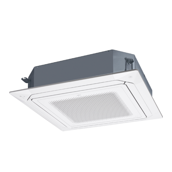
AirStage AUXM018GLEH 설치 매뉴얼 - 페이지 9
{카테고리_이름} AirStage AUXM018GLEH에 대한 설치 매뉴얼을 온라인으로 검색하거나 PDF를 다운로드하세요. AirStage AUXM018GLEH 13 페이지.

Push mount cable tie (accessories)
(4) Replace the Control box
cover and Wiring cover.
Securely tighten the
screws.
Cure the wiring connecting
port and remote controller
connecting port with putty or
heat insulation so that insects
or dust will not enter the unit.
Do not bundle the remote controller cable, or wire the remote controller cable in parallel,
with the indoor unit connection wire (to the outdoor unit) and the power supply cable. It
may cause erroneous operation.
6.5. Optional parts wiring
6.5.1. Layout of the indoor unit PCB
CN67
CNA03
CNB01
CNA01
CNA02
CNA04
Power indicator
lamp (green)
Name
CNA01
Apply voltage terminal
CNA03
CNA02
Dry contact terminal
CNA04
DIP switch SET 2 (SW2)
Input signal type switching
CNB01
Output terminal
CN65
For one of the following.
• MODBUS® convertor (*1)
• Wireless LAN adapter (*1)
CN67
For Human sensor kit
CN820
For External power supply unit (*1)
*1: For details, refer to each installation manual.
X1, X2: Transmission cable
Cut
Y1, Y2: Remote controller cable
(do not use Y3.)
CAUTION
CN820
CN65
Controller PCB
SET 2
ON
DIP switch
OFF
(SET 2)
SW1
SW3
SW2
SW4
Application
For external input
For external output
6.5.2. Power indicator lamp status
Power indicator lamp (Green)
Lit
Lit when the power is turned on.
Fast flashing (every 0.1 sec-
There is a fault with the communication board or the
ond)
main board.
The indoor unit is turned off and power is supplied
Blinking (repeat 3 seconds ON
from the External power supply unit (optional) to the
and 1 second OFF)
indoor unit PCB.
6.5.3. Connection methods
Wire modification for External
input/output wire
(1) Remove insulation from wire at-
tached to wire kit connector.
(2) Remove insulation from field
supplied cable. Use crimp type
insulated butt connector to join field
cable and wire kit wire.
(3) Connect the wire with connecting
wire with solder.
Wiring arrangement
In following figure, all the possible connectors are connected for description.
In actual installation, you cannot connect all the connectors at once.
Cable hooks
Cable clamp
6.6. External input and external output (Optional parts)
6.6.1. External input
• Indoor unit can be Operation/Stop, Emergency stop or Forced stop by using indoor unit
PCB CNA01 or CNA02.
• "Operation/Stop" mode, "Emergency stop" mode or "Forced stop" mode can be selected
with function setting of indoor unit.
• Indoor unit can be Forced thermostat off by using indoor unit PCB CNA03 or CNA04.
• A twisted pair cable (22 AWG) should be used. Maximum length of cable is 150 m.
• Use an external input and output cable with appropriate external dimension, depending
on the number of cables to be installed.
• The wire connection should be separate from the power cable line.
Input select
Use either one of these types of terminal according to the application. (Both types of
terminals cannot be used simultaneously.)
● Apply voltage terminal ([CNA01], [CNA03])
When a power supply must be provided at the input device you want to connect, use the
Apply voltage terminal ([CNA01], [CNA03]).
DC power supply
12 to 24V
Load
resistance
*a
Load
resistance
*a
Load
resistance
*a
Connected unit
*1: Make the power supply DC 12 to 24 V. Select a power supply capacity with an ample
surplus for the connected load.
Do not impress a voltage exceeding 24 V across pins 1-2, and 1-3.
*a: The allowable current is DC 5 mA to 10 mA. (Recommended: DC 5 mA)
Provide a load resistance such that the current becomes DC 10 mA or less.
Select very low current use contacts (usable at DC 12 V, DC 1 mA or less).
*b: The polarity is [+] for pin 1 and [-] for pin 2 and 3. Connect correctly.
Status contents
IMPORTANT:
Be sure to insulate the connection between the
wires.
Locally
Wire kit connector
purchased
(optional parts)
Solder and insulate the connected parts.
P.C.B
*1
CNA01
*b
CNA03
En-8
