Bosch 800 Series 설치 지침 매뉴얼 - 페이지 9

{카테고리_이름} Bosch 800 Series에 대한 설치 지침 매뉴얼을 온라인으로 검색하거나 PDF를 다운로드하세요. Bosch 800 Series 40 페이지. Built-in wall ovens
Bosch 800 Series에 대해서도 마찬가지입니다: 설치 지침 매뉴얼 (24 페이지), 설치 매뉴얼 (40 페이지), 사용 및 관리 매뉴얼 (12 페이지), 설치 매뉴얼 (23 페이지), 설치 매뉴얼 (28 페이지), 설치 매뉴얼 (32 페이지), 사용 설명서 (32 페이지), 설치 매뉴얼 (32 페이지), 빠른 시작 및 안전 매뉴얼 (7 페이지), 사용 및 관리 매뉴얼 (40 페이지), 설치 매뉴얼 (40 페이지), 설치 매뉴얼 (32 페이지), 설치 매뉴얼 (48 페이지), 사용 및 관리 매뉴얼 (33 페이지), 사용 및 관리 매뉴얼 (49 페이지), 빠른 시작 매뉴얼 (7 페이지), 빠른 시작 및 안전 매뉴얼 (13 페이지), 설치 매뉴얼 (32 페이지), 서비스 매뉴얼 (36 페이지), 설치 지침 매뉴얼 (29 페이지), 사용 및 관리 매뉴얼 (24 페이지), 사용 및 관리 매뉴얼 (40 페이지), 설치 지침 매뉴얼 (28 페이지)
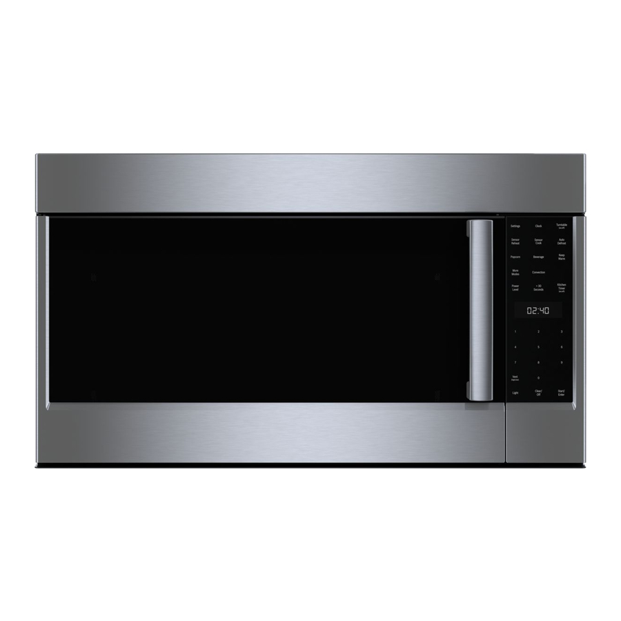
Bosch 800 Series 설치 지침 매뉴얼

Appliance dimensions

A
Only for circulating-air mode:
*Max. 42 9/16" (1081 mm)
*Min. 28 1/4" (718 mm)
Only for ducted operation:
*Max. 38 7/8" (988 mm)
*Min. 24 9/16" (625 mm)

Safety clearances

WARNING
RISK OF FIRE
Grease deposits in the grease filter can catch fire.
The given safety clearance must be observed to
avoid heat buildup. Observe the specifications for
your cooking appliance. If gas and electric cooktops
are used together, the largest given clearance
applies.
The appliance may only be installed directly next to
a cabinet or wall on one side. The wall or cabinet
clearance must be at least 2" (50 mm).
The clearance between the shelf on the cooktop and the
bottom of the extractor hood may not be less than 24"
(610 mm) in the case of electric cooktops and 30"
(760 mm) in case of gas or combined ranges.
If the installation instructions for the gas cooking
appliance specify a larger distance, this must be taken
into account.
7
7
/
"
8
(200 mm)
Electrical cooktop
Gas cooktop

Fan operation

Note: Ventilation may not exit through an already
operational smoke or exhaust chimney, nor a duct used
for ventilating furnace installation areas.
If the ventilation is intended to pass through a smoke
or exhaust chimney that is not in operation, the
responsible area heating inspector must give approval.
If the ventilation passes through an external wall, use a
telescope wall sleeve.

Ventilation line

Note: The device manufacturer is not responsible for the
operation or complaints associated with the pipe section.
The ventilation opening and the exhaust air ducts must
be made according to the local requirements.
The device achieves its optimum performance by
means of a short, straight exhaust air pipe and as
large a pipe diameter as possible.
As a result of long rough exhaust air pipes, many pipe
bends or too-small diameters, the optimum extraction
performance is not achieved and fan noise is
increased.
The pipes or hoses for laying the exhaust air line must
consist of non-combustible material.
Smooth the connection area of the pipes before
installation.
Seal the connection points of the pipes appropriately.
9