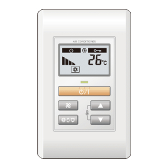
AirStage UTY-RSKYT 설치 매뉴얼 - 페이지 6
{카테고리_이름} AirStage UTY-RSKYT에 대한 설치 매뉴얼을 온라인으로 검색하거나 PDF를 다운로드하세요. AirStage UTY-RSKYT 9 페이지. Simple remote controller
AirStage UTY-RSKYT에 대해서도 마찬가지입니다: 운영 매뉴얼 (2 페이지), 운영 매뉴얼 (2 페이지)

6. INSTALLATION METHODS
6.1. Group control
(1) Wiring method (indoor unit to remote controller)
● Type A (Terminal block)
Indoor unit
Y1 Y2 Y3
Remote
controller cable
When there is a
functional earthing
cable (UTY-RSKYT)
1 2 3
Remote controller
A number of indoor units can be operated at the same time using a single
remote controller.
● Type A (Terminal block)
Indoor unit 0
When there
Y1 Y2 Y3
is a functional
earthing cable
(UTY-RSKYT)
1 2 3
Remote controller
● Type B (Connector)
Indoor unit 0
Remote
controller cable
When there is
a functional
earthing cable
(UTY-RSKYT)
1 2 3
Remote controller
(2) Remote controller address setting of indoor unit
Set each remote controller address using the switch of each indoor unit in order from 0.
(Refer to the installation manual for the indoor unit.)
Up to 16 indoor units can be connected.
En-5
● Type B (Connector)
Indoor unit
Remote
controller cable
Connector
When there
is a functional
earthing cable
1 2 3
(UTY-RSKYT)
Remote controller
Indoor unit 2
Indoor unit 1
Indoor unit 3
Y1 Y2 Y3
Y1 Y2 Y3
Remote controller cable
Indoor unit 2
Indoor unit 1
Indoor unit 3
Connector
Connection
6.2. Dual remote control
•
2 remote controllers can be used to operate the indoor units.
•
The timer cannot be used on the slave units.
•
ADDRESS SETTING and FUNCTION SETTING cannot be used on the slave units.
•
The remote controller (UTB- * LA) and remote controller (UTB- * U * ,
UTB- * P * , UTB- * R * ) cannot be connected at the same time.
(1) Wiring method
(Indoor unit to remote controller)
● Type A (Terminal block)
When there are
functional earthing
cable (UTY-RSKYT)
● Type B (Connector)
Y1 Y2 Y3
Remote
controller cable
When there are
functional earthing
cable (UTY-RSKYT)
(2) Remote controller DIP Switch 1- No. 2 setting
Set the remote controller DIP switch 1- No. 2 according to the following
table.
Number of remote
controllers
1 (Single)
2 (Dual)
•
Group control and dual remote control can be used together.
•
When connecting 2 remote controllers, the remote controller can also be
connected together with another type of remote controller.
M
Indoor unit
Y1 Y2 Y3
1 2 3
Master
unit
Remote controller
Indoor unit
Connector
1 2 3
Master
unit
Remote controller
Master unit
DIP switch 1 - No. 2
OFF
OFF
E
T
Remote
controller cable
1 2 3
Slave
unit
Connection
1 2 3
Slave
unit
Slave unit
DIP switch 1 - No. 2
–
ON
H
-
