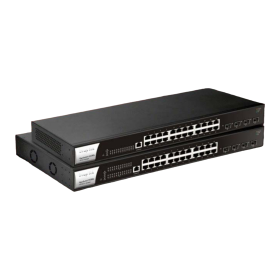
Draytek VigorSwitch G2280x 빠른 시작 매뉴얼 - 페이지 5
{카테고리_이름} Draytek VigorSwitch G2280x에 대한 빠른 시작 매뉴얼을 온라인으로 검색하거나 PDF를 다운로드하세요. Draytek VigorSwitch G2280x 9 페이지. L2+ managed switch
Draytek VigorSwitch G2280x에 대해서도 마찬가지입니다: 빠른 시작 매뉴얼 (12 페이지), 빠른 시작 매뉴얼 (9 페이지)

2
.
P
a
n
e
l
E
2
.
P
a
n
e
l
E
V
i
g
o
r
S
w
i
t
c
h
V
i
g
o
r
S
w
i
t
c
h
LED
Monitor
SYS
PWR
Port 1~24
(GbE RJ45)
Port 25~28
(SFP+)
Interface
Port 1~24 (GbE RJ45)
Port 25~28 (SFP+)
Console
x
p
l
a
n
a
t
i
o
n
x
p
l
a
n
a
t
i
o
n
G
2
2
8
0
x
G
2
2
8
0
x
Status
Explanation
An alert for system failure due to overheating or
On (Red)
wrong voltage.
The device is in normal condition and running
Off
normally.
The switch finishes system booting and the
On (Green)
system is ready.
Blinking
The switch is powered on and starts system
(Green)
booting.
The power is off or the system is not ready /
Off
malfunctioning.
On (Green)
The device is powered on and running normally.
Off
The device is not ready or is failed.
On (Green)
The device is connected with 1000Mbps.
On (Amber)
The device is connected with 10/100Mbps.
Blinking
The data is transmitting.
Off
The port is disconnected or the link is failed.
On (Green)
The device is connected with 1000Mbps.
On (Blue)
The device is connected with 10Gbps.
On (Amber)
The device is connected with 10/100Mbps.
Blinking
The data is transmitting.
Off
The port is disconnected or the link is failed.
Description
Port 1 to Port 24 can be used for Ethernet
connection, depending on the device connected
Port 25 to Port 28 are used for fiber connection.
Used to perform telnet command control.
Power inlet for AC input (100~240V/AC,
50/60Hz).
2
.
