Carlin 60200 매뉴얼
{카테고리_이름} Carlin 60200에 대한 매뉴얼을 온라인으로 검색하거나 PDF를 다운로드하세요. Carlin 60200 4 페이지. Cad cell oil primary control
Power input (red/white wire)
Limit circuit input (black wire)
Motor load
Ignitor load
Valve load
Alarm contacts
Installing and Wiring
The 60200 control must be installed and serviced only by a qualified service technician.
1. Always disconnect power source before wiring to avoid electrical shock or damage to the control. All wiring must comply with
applicable codes and ordinances.
2. Thermostat terminals (T-T) provide a current source. Never apply external power to these terminals under any circumstances.
3. Alarm terminals provide a 24 VAC/VDC-rated dry contact.
Mounting
• The control may be mounted on a 4" x 4" junction box in any convenient location on the burner, furnace or wall. The location
must not exceed the ambient temperature limit, 140°F.
Wiring
• Wiring must comply with local and national electrical codes, and with the wiring diagram.
• Individual or bundled neutrals may be attached to any L2 terminal.
Field checks
1. Safety timing (TFI) test – Remove one CAD cell wire (F-F). Start burner. The control should lockout within the TFI time limit.
Replace CAD cell wire.
2. Flame failure test – Start burner. After flame is established (after TFI period), close the oil supply hand valve. This will cause a
flame failure sequence as described in the Startup & Operation section of this Data sheet. The control should recycle (restart after
65 seconds).
3. If control does not operate as described, check the wiring.
Startup & Operation
Do not start the burner if the combustion chamber
contains oil or oil vapor.
Per UL requirements, the control will not turn on if the
CAD cell senses flame during the self-test. If the CAD cell sees light (flame) at the beginning of a cycle, the control will remain in
self-test mode until the CAD cell no longer senses light (flame). The amber LED will blink momentarily
green LED will be on or flashing.
Tech Support (800) 989-2275
• Oil Pump Bleed Assist
60 seconds
• CAD Cell Resistance Monitoring Jack
Works with any multimeter
• Recycle on Flame Failure
• Serviceman Reset Protection
Latch-up after 3 consecutive lockouts
• Diagnostic LEDs
Status, lockout, flame
• 15-second, 30-second TFI
120 VAC, 60 HZ, 9VA
120 VAC, 60 HZ
10 FLA / 60 LRA
120 VAC, 60 HZ, 500 VA
120 VAC, 60 HZ, 2.0 A
24 V, AC/DC, 2A
SEE WIRING DIAGRAM ON NEXT PAGE
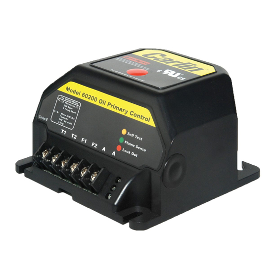
Model 60200 CAD Cell Oil
Primary Control Data Sheet
• Increased Flame Accuracy
• Thermostat/Aquastat Compatible
• Improved SMC Technology
Zero bleed voltage during standby
• Works Well with Generators
Insensitive to frequency changes
• Early Spark Termination
• Alarm Contacts
• Flame Signal Test Jack
Nozzle Line Heater
Operating temperature limits
Storage temperature limits
Thermostat anticipator current
CAD cell resistance (with flame)
Agencies
Model 60200 Diagnostic LEDs
– Amber OFF
– Amber ON
– Green OFF
– Green ON
– Red OFF
– Red ON
www.carlincombustion.com
(optional)
120 VAC, 60 HZ, 1 amp
+32°F to +140°F
-40°F to +185°F
0.1 A, AC
R < 1500 OHMS
UL recognized (US & Canada)
– Amber FLASHING
– Green FLASHING
– Red FLASHING
every 3 to 4 seconds and