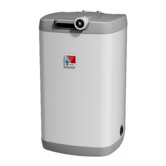
Drazice OKH 125 NTR 작동 및 설치 매뉴얼 - 페이지 8
{카테고리_이름} Drazice OKH 125 NTR에 대한 작동 및 설치 매뉴얼을 온라인으로 검색하거나 PDF를 다운로드하세요. Drazice OKH 125 NTR 16 페이지. Tank type indirect water heaters
Drazice OKH 125 NTR에 대해서도 마찬가지입니다: 작동 및 설치 매뉴얼 (14 페이지), 운영 및 설치 매뉴얼 (17 페이지), 작동 및 설치 매뉴얼 (12 페이지)

2 OPERATION AND FITTING INSTRUCTIONS
2.1 OPERATING CONDITIONS
The tank shall only be used in accordance with the conditions specified on the performance
plate and in instructions for electric wiring.
regulations and standards, also conditions for connection defined in local electric and water
works have to be adhered to, as well as the installation and operation manual. The room, in
which the appliance will be operated, must be frost-free. The appliance has to be mounted
at a convenient place, it means that the appliance must be easily available for potential
necessary maintenance, repair or replacement, as the case may be.
If water is strongly calcareous we recommend that any of the common decalcifying devices
was installed with the appliance, or the thermostat to be set to minimum operation
temperature of 60
used. To avoid potential sediments we recommend that the device was installed together
with a water filter.
2.2 PLUMBING FIXTURE
Connecting storage tanks into water system in shown in Figure 5. For potential
disconnection of the storage tank, the service water inlets and outlets must be provided
with screw coupling Js 3/4".If the hot service water (HSW) distribution is equipped with
circulation circuit, the reverse pipe is connected to the inlet identified as CIRCULATION. The
100, 125, 160 NTR and 100, 125, 160 NTR / HV types are equipped with a discharge outlet.
For operation, the storage tank must be equipped with a safety valve. Safety valve is
mounted on the cold water inlet identified with a blue ring
Each hot service water pressure storage tank must have a safety valve with a membrane
spring. The safety valve must be easily accessible, as close to the storage tank as possible.
The input pipes must have at least the same clearance as the safety valve. The safety valve is
placed high enough to secure dripping water drain by gravity. We recommend mounting the
safety valve onto a branch pipe. This allows easier exchange without having to drain the
water from the storage tank. Safety valves with fixed pressure settings from the
manufacturer are used for the assembly. Starting pressure of a safety valve must be identical
to the maximum allowed storage tank pressure, and at least 20% higher than the maximum
pressure in the water main - see (Table 2). If the water main pressure exceeds such value, a
reduction valve must be added to the system. No stop valves can be put between the
storage tank and the safety valve. During the assembly, follow the guide provided by the
safety equipment manufacturer
o
C. For proper operation, drinkable water of adequate quality shall be
Besides legally acknowledged national
- 8 -
