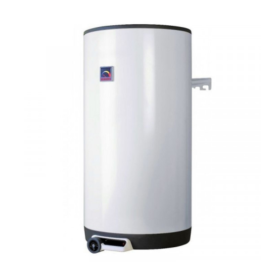
Drazice OKC 125 NTR 작동 및 설치 매뉴얼 - 페이지 2
{카테고리_이름} Drazice OKC 125 NTR에 대한 작동 및 설치 매뉴얼을 온라인으로 검색하거나 PDF를 다운로드하세요. Drazice OKC 125 NTR 12 페이지. Tank-type water heaters for vertical mounting
Drazice OKC 125 NTR에 대해서도 마찬가지입니다: 작동 및 설치 매뉴얼 (17 페이지), 작동 및 설치 매뉴얼 (20 페이지), 작동 및 설치 매뉴얼 (20 페이지), 작동 및 설치 매뉴얼 (18 페이지), 운영 및 설치 매뉴얼 (20 페이지), 작동 및 설치 매뉴얼 (18 페이지)

Read carefully the below instructions prior to the installation of the
heater!
Dear Customer,
The Works Cooperative of Dražice - Machine Plant, Ltd., would like to thank you for your decision to use a
product of our brand.
The manufacturer reserves the right for engineering modification of the product.
The product is designed for permanent contact with drinkable water.
Guide Contents
1.
FUNCTION DESCRIPTION ............................................................................................................ 2
2.
MESSAGE FOR CUSTOMERS ....................................................................................................... 3
3.
TECHNICAL DESCRIPTION ......................................................................................................... 3
4.
OPERATING ACTIVITY ................................................................................................................. 3
5.
SERVICING ........................................................................................................................................ 4
6.
WALL MOUNTING .......................................................................................................................... 5
7.
PLUMBING FIXTURE ..................................................................................................................... 5
8.
CONNECTION OF COMBINED HEATER TO HOT WATER HEATING SYSTEM ............. 6
9.
ELECTRIC INSTALLATION .......................................................................................................... 6
10. PUTTING THE HEATER INTO OPERATION ............................................................................ 6
11. HEATER CLEANING AND ANODE ROD EXCHANGE ............................................................ 6
12. IMPORTANT NOTICES .................................................................................................................. 7
14. INSTALLATION REGULATIONS ................................................................................................. 7
15. MOST FREQUENT FUNCTION FAILURES AND THEIR CAUSES ....................................... 8
16. PRODUCT ACCESSORIES ............................................................................................................. 8
17. TECHNICAL DATA CHART...........................................................................................................9
18. PICTURES........................................................................................................................................10
Environment Type:
It is recommended to use the product in indoor environment with air temperatures from +2°C to 45°C and a
relative humidity up to 80%.
1.
FUNCTION DESCRIPTION
The heater is designed for accumulation heating of service water using electricity or thermal energy via an
exchanger (for the combined design only).
Water is heated by an electric element (or a heat exchanger) in an enamelled thermally insulated accumulator at
the time defined by the power supplier. The element is at the time of heating controlled by a thermostat the
temperature of which can be adjusted continuously (within the range between 5°C and 74°C). Once the selected
temperature is reached, heating interrupts automatically.
Water accumulated in the tank is then used for consumption. The tank keeps constant pressure of water from
the water main. If the combination faucet hot water valve is opened, water from the water supply conduit pressed
out by cold water pressure flows out of the heater. Hot water flows out through the top part, and water flowing in
remains in the bottom part of the heater. Pressure principle allows hot water withdrawal at any place from the
heater (Fig. 1).
2
