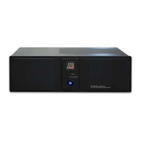
ATI Technologies AT52XNC 소유자 매뉴얼 - 페이지 7
{카테고리_이름} ATI Technologies AT52XNC에 대한 소유자 매뉴얼을 온라인으로 검색하거나 PDF를 다운로드하세요. ATI Technologies AT52XNC 14 페이지. Class d 2 to 8-channel

Connecting Your Amplifier
When making connections between any source compo-
nents and the amplifier, or when making connections to
any speaker, be certain that both the input devices and
the amplifier are turned off. To assure that there will be
no unwanted signal transients that can damage equip-
ment or speakers, it is always best to unplug all equip-
ment before making any connections.
Input Connections
Connecting the amplifier to your source equipment is
simple. Using high-quality audio interconnect cables,
match the output channel designations on the rear of
your source equipment to the input jacks on the rear
panel of your amplifier that have the same channel
name. The AT500
amplifiers have both XLR and
NC
RCA input connections on the rear panel. Use the tog-
gle switch to the right of each RCA jack to select the
desired input for each channel. When making connec-
tions with RCA type plugs on interconnect cables,
make certain to gently, but firmly, insert the plug into
the jack. Loose connections can cause intermittent
sound and may damage your speakers. Some quality
RCA plugs may be very tight, and it is important to
assure a proper connection between the interconnection
cable and the input jack.
Speaker Connections
Warning: There are two versions of the AT500
ries amplifier. One is a conventional single-ended
ground referenced configuration. These are the
AT522
- AT528
. The other is a balanced bridge
NC
NC
amplifier in which the negative speaker terminal is
NOT a ground and cannot be connected to a system
ground or to a loudspeaker system with a common
ground.
The
balanced
AT542
; AT543
and AT544
NC
NC
Before connecting speakers to any of the AT54X
models
consult your speaker manufacturer to ensure
,
that any speaker in your system that will be connected
to these balanced bridge amplifiers does NOT have
internal circuitry with a common ground.
To assure that the high quality signals produced by
your amplifier are carried to your speakers without loss
of clarity or resolution, we recommend that you use
high quality speaker wire. Many brands of wire are
available; the choice may be influenced by the distance
between your speakers and the amplifier, the type of
speakers you use, personal preferences, or other factors.
Regardless of the brand or type of speaker wire select-
ed, we recommend that you use a wire constructed of
fine, multi-strand copper with a gauge of 14 or less. In
specifying wire, the lower the number, the thicker the
AT500NC Manual
Se-
NC
bridge
amplifiers
are:
.
NC
NC
cable. Wire with a gauge of 16 may be used for short
runs of less than twenty feet. We do not recommend
that you use any wires with an AWG equivalent of 18
or higher due to the power loss and degradation in per-
formance that will occur.
To connect the amplifier to your speakers, a pair of
binding posts is provided for each channel output.
These posts will accept bare wire, spade lugs or banana
type plugs. If bare wire is used for the connections,
strip approximately 1/2 inch to 3/4 inch of insulation
from the end of each wire and carefully twist the
strands of each conductor together. Be careful not to
cut the individual strands or twist them off. All strands
must be used for optimal performance.
Correct polarity of connections are important to main-
tain proper speaker phasing. When speaker phasing is
correct, all speakers move in and out at the same time,
preserving the imaging of the program material. Out-of
-phase connections mean that some speaker cones will
be moving in, while others move out. This will cause
indistinct or confused imaging, and muddled and
cloudy sounds. To avoid incorrect phasing or polarity,
be certain to use wire that has distinct markings, colors,
stripes, wording, or grooves on each side of the speaker
cable. When making connections to the amp and speak-
ers, adhere to a consistent pattern of using one side of
the wire to the red terminals and the other side to the
black terminals. When using cable with markings on
one side only, traditional convention is to consider the
marked side of the wire as the red, or positive (+) con-
nection, and the non-marked side as the black or nega-
tive (–) connection.
Next, loosen the knobs of the amplifier's speaker out-
put terminals, far enough so that the pass through hole
is revealed. Follow the proper connection instructions
for your system with regard to which terminals are
used. Once the connections are made, twist the cap
back so that the connection is secured, but do not over
tighten or use tools, as this may break the delicate wire
strands and decrease system performance.
If you are using spade lugs, connect them to the speak-
er wire using the manufacturer's instructions, and then
loosen the caps on the speaker terminals. Place lugs
between the plastic cap and the back of the terminal. Be
sure to observe proper polarity, using the appropriate
speaker hook-up icons for your system's configuration.
Using your fingers, tighten to obtain a positive contact.
When using banana plugs, connections may be made
by simply inserting the jack affixed to your speaker
wire into the hole provided on the rear of the colored
screw caps on the binding posts. Before using banana
type jacks, make certain that the plastic screw caps are
firmly tightened down by turning them in a clockwise
direction until they are snug against the chassis. This
6
Rev-05/18
