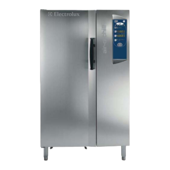
Electrolux AOFP101U 매뉴얼 - 페이지 11
{카테고리_이름} Electrolux AOFP101U에 대한 매뉴얼을 온라인으로 검색하거나 PDF를 다운로드하세요. Electrolux AOFP101U 11 페이지. Bcf 30kg 6 gn1/1 lw (240/3/60hz), bcf 50kg 10 gn1/1 lw (240/3/60hz) / bcf 100kg 20 gn1/1 lw (240/3/60hz) / bcf 70kg 10 gn2/1 lw (240/3/60hz) / bcf 180kg 20 gn2/1 lw (240/3/60hz) / bcf 30kg 6 gn1/1 lw (208/3/60hz) / bcf 50kg 10 gn1/1 lw (208/3/60hz) / bcf
Electrolux AOFP101U에 대해서도 마찬가지입니다: 운영 및 유지보수 지침 매뉴얼 (27 페이지)

Pumping for remote control unit (AOFP201RU - 20 GN 1/1)
Liquid gas line 0.47" dia (12 mm)
Gas intake line 0.79" dia (20 mm)
Lay the copper piping, choosing the shortest route and avoiding
bends, elbows and vertical stretches as much as possible,
observing the following rules:
- in the horizontal stretches, the intake line must slope down to
the condenser unit at a gradient of not less than 2%.
- air traps must be installed before all upward stretches of the
intake line (every 6.6 feet/2 metres).
- insulate the intake line with suitable lagging (minimum
thickness 0.35 in / 9 mm).
- you are advised to install the remote unit at a distance of no
more than 49.21 feet/15 m. from the appliance, and with a
maximum height difference between unit and appliance of 5
m. IF YOU EXCEED THESE DISTANCES, PLEASE CONSTULT
YOUR CONTACTOR FOR INFORMATION ON INSTALLATION.
• Install the following devices on the gas liquid line, in the
following order: a filter, a suitably sized dehydration (dryer)
device, a liquid flow indicator and a solenoid valve.
B.1.6 ELECTRICAL CONNECTION
In the case of equipment with remote units, the connection must
be made separately for the unit and the appliance.
The AOFP201RU models are all remotely controlled and run on
three-phase power supply (208V, 3ph, 60Hz).
The AOFP061U, AOFP061TU, AOFP101U, AOFP102U models
run on three-phase power supply (208V, 3ph, 60Hz).
CAUTION:
Connection to the electrical mains must be carried out in
accordance with current regulations and the standards re-
quired by the National Electric Code (NEC), known as NFPA 70.
Before connecting, make sure that:
- The appliance must be hard wired to incoming power supply.
- In order to protect the appliance from possible leakages,
overloads or short-circuits, install a circuit-breaker or fused
disconnect switch between the power supply cable and the
main power source.
- After making the connection and with the appliance running,
check that the rated voltage level does not fluctuate by ± 10%.
Note: In the models set up for operation with remote units,
make the electrical connection to the condenser unit and solenoid
valve as illustrated in the wiring diagram enclosed with the
appliance.
The wire connection must be sized with correct cable for the
amperage. Insert the wires and clamp them with the special
cable clamp. Correctly connect each wire to the corresponding
terminal.
The manufacturer will accept no liability for any damage or
injury resulting from the violation of the above rules or of the
binding electrical safety standards in the country where the
appliance is used.
B.1.7 PUTTING THE LINES UNDER VACUUM AND CHARGING
WITH REFRIGERANT GAS (FOR REMOTE UNITS)
B.1.7.1 Leakage test
- Wash out the intake pipes with pressurised dry nitrogen.
- Connect a nitrogen cylinder to the high and low pressure
connectors, and connect to a pressure gauge (using a "T"
union). Charge the high and low pressure lines with gas until
they reach a pressure of about 217.56 psi/15 bar. Shut off the
cylinder cock and, after at least an hour, check that the pressure
has not dropped to below the previous reading level.
B.1.7.2 Vacuum
- Empty the circuit manually by opening the connectors.
- Connect the pipes to a vacuum pump, preferably a two-stage
model with a vacuum gauge and high and low pressure
connectors. Take the vacuum level to equal to or lower than
70Torr (0.093bar). On reaching this level, stay at the same level
for about 30 minutes and then proceed with charging the unit as
follows:
B.1.7.3 Charging with refrigerant
- Charge the high and low pressure lines with liquid refrigerant
for R404A until the pressure between the cylinders and the
circuit is balanced (The initial charge of fluid is about 20 to 30%
of the total charge).
- At this point, shut off the high pressure line, start up the
compressor and charge with gas slowly until the bubble in the
liquid indicator disappears.
CAUTION:
the charging with refrigerant must be done by professionally
qualified personnel.
B.1.8 Checks to be made when starting up the appliance
- Before making the appliance operational, run a complete
manual cooling or blast chilling cycle.
- Use the liquid flow indicator to check that the circuit is sufficiently
charged.
If ok, proceed with start-up, or if not, complete the charging
following the instructions in § B.1.7.3.
- Using a digital thermometer, check that the temperature
reading on the control panel matches the thermometer reading.
- In condensing units, it is advisable to check the correct return
of oil to the compressor. The check can be made in the
following way:
1. with the condensing unit turned off, make sure that the
oil window located on the compressor casing is filled to
at least 1/4 its height.
2. run a complete empty HARD CHILLING (BC) or
FREEZING (BCF) cycle;
3. turn the chiller off at the end of the cycle;
wait at least 15 minutes then check the oil level. The oil
must be visible in the window on the oil casing; if not, add
oil until filled to at least 1/2 its height (only use oil with the
characteristics given on the compressor dataplate).
19
