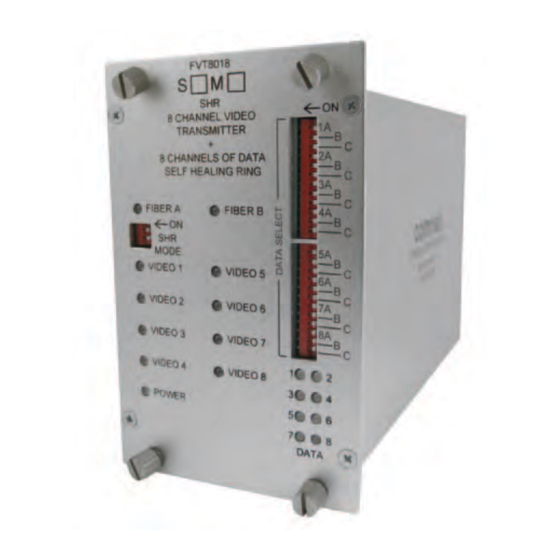
Comnet FVR8018SHR 설치 및 운영 매뉴얼 - 페이지 8
{카테고리_이름} Comnet FVR8018SHR에 대한 설치 및 운영 매뉴얼을 온라인으로 검색하거나 PDF를 다운로드하세요. Comnet FVR8018SHR 11 페이지. 8-channel 10-bit digitally encoded video + 8-channel bi-directional data + self-healing ring topologies

INSTALLATION AND OPERATION MANUAL
FIGURE 11 – EXAMPLE SYSTEM IN LINEAR TOPOLOGY
A
The figure below shows a system with FVT/FVR1010SHR units connected in a linear topology. The system demonstrates a video distribution application.
A single video input is transmitted by a FVT1010SHR over fiber optic cable to three daisy-chained FVR1010SHR units. The last unit in the chain is
connected to an audible alarm to indicate faults.
Three receivers are used in this example, but there is no limit to the number of receivers used in a system. This example could also be expanded to
distribute four or eight channels of video using FVT/FVR4014SHR or FVT/FVR8018SHR units, respectively.
A
B
FVT1010SHR
Unit 1
VIDEO IN
V
B
The table below shows the SHR configuration switches for each unit in the system. once the system is configured, all of the PoWER, oPTIC and VIdEo
lEds will be solid green except for the oPTIC A lEd on Unit 1 and the oPTIC b lEd on Unit 4, which would both be solid red. No faults will be reported
because RFl has been disabled at Units 1 and Unit 4. The alarm relay will be closed.
SHR Switch
Unit
1
2
3
1
ON
ON
ON
2
ON
ON
ON
3
ON
ON
ON
4
ON
ON
ON
C
let's consider how the system would respond to a broken fiber between Units 2 and 3:
A
B
FVT1010SHR
Unit 1
VIDEO IN
V
D
The video would no longer be displayed at Units 3 and 4 because this is system has a linear topology (i.e. there is no redundant fiber path).
The alarm relay will open and cause the audible alarm at Unit 4 to sound. In addition, the other units in the system would indicate the location of the
fault using their oPTIC lEds as described in the table below.
Unit OPTIc A LED
1
Solid Red
2
Solid Green
3
Solid Red
4
Green, then blink Red 1 time
TEcH SUPPORT: 1.888.678.9427
A
FVR1010SHR
Unit 2
VIDEO OUT
V
Notes
4
ON
Transmit video on Channel 1. do not report fiber faults to other units.
OFF Receive video from Channel 1.
OFF Receive video from Channel 1
ON
Receive video from Channel 1. do not report fiber faults to other units.
A
FVR1010SHR
Unit 2
VIDEO OUT
V
OPTIc B LED
Green, then blink Red 1 time
Solid Red
Solid Green
Solid Red
A
B
FVR1010SHR
Unit 3
VIDEO OUT
V
B
A
FVR1010SHR
Unit 3
FIBER
BREAK
NO VIDEO
V
FVT/FVR8018SHR
A
B
FVR1010SHR
Unit 4
VIDEO OUT
V
B
A
FVR1010SHR
Unit 4
NO VIDEO
V
INS_FVT/FVR8018SHR_REVA
B
ALARM
B
ALARM
11/14/11
PAGE 8
