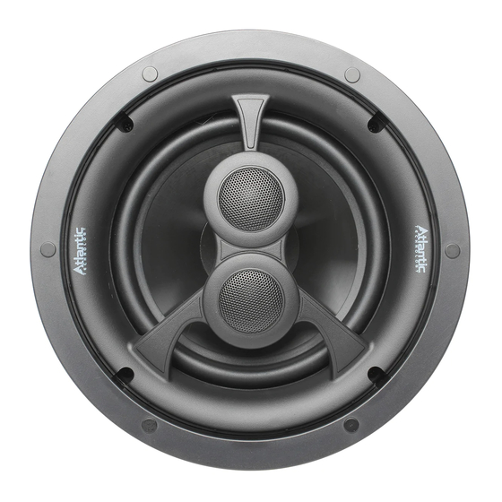
Atlantic Technology IC Series 사용 설명서 - 페이지 4
{카테고리_이름} Atlantic Technology IC Series에 대한 사용 설명서을 온라인으로 검색하거나 PDF를 다운로드하세요. Atlantic Technology IC Series 12 페이지. Thin bezel ceiling speakers

4
Distributed Audio Speaker Placement
Distributed Audio Placement
Atlantic Technology loudspeakers possess extremely smooth and predict-
able off-axis frequency response. However, in some cases, where the room
is large, you may wish to consider the use of two (or more) pairs of speak-
ers in order to provide a wider and more even dispersion of sound. A more
even distribution of sound in this way means that people within the room
are more likely to be equidistant from the speakers so that there are less
"hot" or "cold" spots of audio volume.
When connecting more than one pair of speakers to an amplifier it is vital
to maintain a compatible impedance load between the amplifier and speak-
ers. Your amplifier will specify an acceptable impedance range which it can
handle and you must ensure you do not drop the total impedance below
that specified minimum level or you may damage your amplifier. If in doubt
you should consult a professional installer or contact Atlantic Technology
directly before commencing installation.
As an example, a typical amplifier may specify an acceptable operational
impedance range of 4 to 8 ohms. If you connect two pairs of Atlantic Tech-
nology 8-ohm loudspeakers in parallel, the impedance you will present to
the amplifier is 4 ohms. This is within acceptable limits of most quality
amplifiers. If you connect them in series, you will present 16 ohms resis-
tance to the amplifier which will reduce the available power, but be a very
"safe" load for the amplifier.
Generally, you should not connect two 4-ohm loudspeakers in parallel,
because then the impedance will be 2 ohms and may damage your ampli-
fier. If they are connected in series, the impedance will be 8 ohms and there-
fore within acceptable limits.
Please note that, much like attaching a trailer to the back of a car, attach-
ing a second set of speakers to an amplifier puts an additional load on the
amplifier (or engine). This makes it work harder for the same performance
or it may simply not have the power to perform satisfactorily. You need to
check the capability of your chosen amplifier before attempting multiple
speaker connection.
5.1 Channel Home Theater Placement
Front of room
towards the front of the theater (see diagram on page 5).
7.1 Channel Home Theater Placement
When using the 6.3 or 8.3 speakers as side and back channel speakers in
a 7.1 channel home theater environment, they should be located directly
alongside the listening area to just slightly (1-2 ft.) behind it. If you are set-
ting them to Dipole, the tweeter with the single leg of the bridge should
face towards the front of the theater (see diagram on page 6). The back
speakers should be behind the listening position, about 1-2 ft. away from
the rear wall if possible.
Generally, the best results are when the .3 back
rear of speaker
speakers are set to Dipole, whether or not the .3 side
BIPOLE
speakers are set to Dipole.
You may use the 6.2 or 8.2 as either side or back
surround speakers, with excellent results, in either
a 5.1 or 7.1 home theater system. If you are mix-
DIPOLE
ing .3 and .2 surround speakers in a 7.1 system, it
is advisable to use the .3's as side surrounds, set to
Dipole. Use the angle tweeter capability on the .2 speakers to aim the tweeter
away from the listeners, towards the wall, to create a more non-localizable,
diffuse surround effect.
LCR Use in a Home Theater
The IC-6 HT is ideally suited for front LCR use in a home theater system
when wall-mounted or free-standing speakers are not desired.
Mount the speakers so that the woofers are angled towards the listening
position. (See diagrams on page 5 and 6)
IC Series Thin Bezel Ceiling Speakers
When using the 6.3 or 8.3 speakers as
side channel speakers in a 5.1 channel
home theater environment, they should
be located directly alongside the listen-
ing area to just slightly (1-2 ft.) behind
it. If you are setting them to Dipole
(see diagram below), the tweeter with
the single leg of the bridge should face
