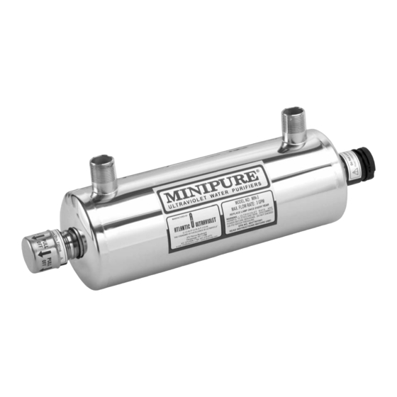
Atlantic Ultraviolet MIN-1 소유자 매뉴얼 - 페이지 8
{카테고리_이름} Atlantic Ultraviolet MIN-1에 대한 소유자 매뉴얼을 온라인으로 검색하거나 PDF를 다운로드하세요. Atlantic Ultraviolet MIN-1 16 페이지. Ultraviolet water purifiers
Atlantic Ultraviolet MIN-1에 대해서도 마찬가지입니다: 소유자 매뉴얼 (16 페이지)

Step 1 - Install Nut on Stud
1.
Plug ballast into an approved Ground Fault Circuit Interrupt (GFCI) receptacle. Where a 2-prong or unprotected 3-prong
receptacle is encountered, it must be replaced by a properly grounded Ground Fault Circuit Interrupt (GFCI) receptacle.
Installation must be in accordance with the National Electrical Code and any local codes and ordinances by a qualified
Electrician.
2.
Once the plumbing hook ups are made, it is a good practice to disinfect the "downstream" plumbing between the purifier and
point of use. This is done by introducing chlorine or other disinfectant solution directly into the purifier chamber, a 100-
ppm of chlorine is suggested. With the disinfectant solution in the purifier chamber, turn the ultraviolet purifier on. Open the
"downstream" outlet until a chlorine or disinfectant solution odor is noticed. Close the outlet and allow the disinfectant to
remain in the plumbing for at least three (3) hours. Flush the plumbing with ultraviolet purified water; allow the water to run
for a minimum of 5 minutes before use (to ensure no chlorine or disinfectant solution smell can be detected), this will allow
the chlorine or disinfectant solution to be flushed through the pipes.
CAUTION: For added protection, a suitable drain pan must be installed under the purifier. The drain pan must be
plumbed to an adequate, free flowing drain to prevent water damage in the event of a leak. There are numerous leak
detection/flood stop devices, available on the market today, designed to stop the flow of water, reducing the chance of
water damage due to leakage. For more details regarding leak prevention and/or limiting damages due to leaks, please
contact the factory.
R
O
ECOMMENDED
1.
Sentry™ Safety Sensor: Indicators provide constant visual monitoring of normal operation. In the event of ballast or lamp
failure the safety sensor indicates an alarm condition. The safety sensor is capable of operating an optional audio alarm and/
or solenoid valve.
2.
Audio Alarm: Activated by the Ultraviolet Monitor or Safety Sensor, alerts the user to any malfunction detected.
3.
Time Delay Mechanism: Provides a 2-minute warm up period during which the ultraviolet lamp achieves its full germicidal
output before the water is allowed to flow through the water purifier. The time delay mechanism is used in conjunction with,
and is electrically connected to the Solenoid Valve.
4.
Solenoid Valve: Operated in conjunction with the Ultraviolet Monitor, Safety Sensor or Time Delay Mechanism, this valve
prevents water flow through the water purifier when an abnormal condition is detected or in the event of power failure.
5.
Sure Flo™ Flow Control Valve: Limits water flow to the rated capacity of the purifier. The flow control valve is located
in line prior to the water purifier, and should be protected from ultraviolet exposure by the use of a 90-degree elbow fitting
between the flow control valve and the water purifier. Unless otherwise specified PVC flow control valves are supplied.
Stainless Steel Flow Control Valves are available for certain models. All PVC and Stainless Steel flow control valves are male
NPT. Consult Factory for other flow control valves
6.
Elapsed Time Indicator: A non-resettable display of the water purifier operating hours. Useful for scheduling and recording
maintenance and lamp replacement.
7.
Safety Goggles: Safety eyewear should be used as general-purpose safety protection and for additional shielding from
Ultraviolet rays
8.
Gloves: Gloves should be worn to offer hand protection from sharp threats like glass, wire, and metal.
NOTE: The recommended options above are available from Atlantic Ultraviolet Corporation or a distributor of Atlantic
Ultraviolet Corporation's products. For the other devices that may be required for your application, please contact your
local water treatment dealer, plumber or plumbing supplier.
8
Step 2 - Slide Ring Terminal Wire
Assembly onto Stud & Lock Washer
over Ring
PTIONS
Step 3 - Install Nut on Stud against
Washer & Tighten with 7/16" Wrench
