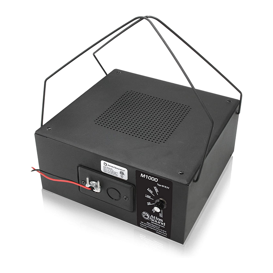
Atlas M1000 설치 지침
{카테고리_이름} Atlas M1000에 대한 설치 지침을 온라인으로 검색하거나 PDF를 다운로드하세요. Atlas M1000 1 페이지. Atlas sound sound masking loudspeaker assemblies specification sheet
Atlas M1000에 대해서도 마찬가지입니다: 사양 시트 (1 페이지), 설치 지침 (1 페이지)

VIBRA‐SONIC CONTROL
SOUND MASKING SYSTEMS
1. After removing speakers from box, lift the hang brackets upward and together.
2. EACH SPEAKER HAS A STEPPED VOLUME CONTROL. TURN THE VOLUME CONTROL
(Wattage) TO 1.0 ON EVERY SPEAKER UNLESS OTHERWISE NOTED ON DRAWINGS. THIS IS VERY IMPORTANT.
3.
The perforated side of the enclosure faces the structural ceiling.
4.
Hang the speakers so the bottom of the enclosure is approximately 6" to 1 foot above the acoustic tile. This is
standard for plenums up to 4' in height, but may vary with different plenum characteristics. For higher plenums
or unique plenums, desired hanging level will be noted on drawings. Chain (supplied) will be required in many
cases to reach the desired hanging level.
5. Speakers must all be hung to the same level unless noted on the drawings.
6. Speakers must be anchored directly to the concrete ceiling or q‐deck.
7. Speakers must hang balanced so speaker face is straight up not at an angle.
8.
If there are plenum "obstacles" in your way move the speaker a bit to the left or right to allow for proper
hanging and sound dispersion.
9. The clearer the plenum area above the speaker the better the sound dispersion.
10. Speakers are installed on a 15 foot grid so if you adjust the installation location for one speaker, try to balance
the next. Please note changes on the drawing.
11. If balancing the distance between speakers is not possible, do the best you can.
12. FT4, 2 conductor, non shielded 18 gauge wire must be used unless the install is in inner Vancouver or Ontario, in
which case FT6, 2 conductor, non shielded 18 gauge wire must be used. NO EXCEPTIONS
13. Wire the speakers in parallel, as shown on the drawing. All wiring must be run neatly, no slack wiring. The final
home run goes to the electrical/telephone/communication room (where the sound equipment will be installed)
as shown on the drawing. Speakers must be continuously wired in a daisy chain process.
14. Run the wires down the wall to the head equipment, attaching wires to the wall or running down through the
wall.
15. If wiring is altered from layout supplied, please send as‐builts to Vibra‐Sonic
16. Label wire ends Sound Masking, Floor & Zone (according to the drawing) for easy connection to the head
equipment. (ie. SM, F10, Z5). Leave a minimum of 25' of home run slack wire neatly coiled for termination.
Vibra‐Sonic Control | 4004 Graveley Street | Burnaby, BC | V5C 3T6 | P: 604‐294‐9495 | F: 604‐294‐8033 | www.vibra‐sonic.com
Installation Instructions for Atlas Sound M1000 Speakers
