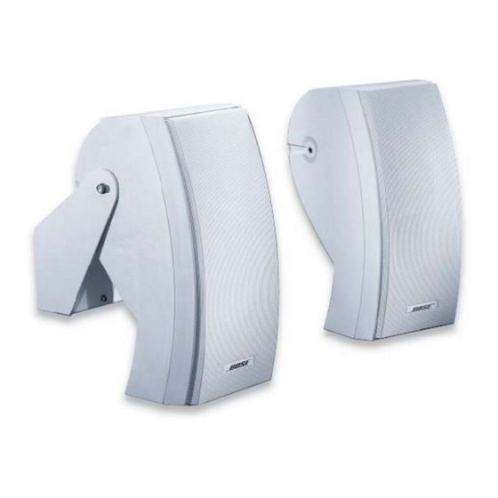
Bose 302 A 서비스 매뉴얼 - 페이지 5
{카테고리_이름} Bose 302 A에 대한 서비스 매뉴얼을 온라인으로 검색하거나 PDF를 다운로드하세요. Bose 302 A 10 페이지. Loudspeaker (commercial indoor/outdoor 70v/100v distributed applications)
Bose 302 A에 대해서도 마찬가지입니다: 설치 관리자 매뉴얼 (13 페이지), 기술 데이터 시트 (2 페이지), 설치 관리자 매뉴얼 (7 페이지)

DISASSEMBLY/ASSEMBLY PROCEDURES
10. Crossover Capacitor Replacement
10.1 Connect the leads of the capacitor (3) to
the wires and solder the connections. The
capacitor is wired in series with the woofer's
(1) positive terminal and the Twiddler
(2) positive terminal. Refer to Figure 1 and 3.
10.2 To prevent air leaks, use a new Twiddler
driver panel (11) and gasket (12). Line up the
Twiddler panel with the cabinet and replace
the four screws (16) that secure it to the
baffle.
The transformer is set at the factory for 70V, 100W operation.
•
To change from 70V to 100V operation, replace the orange wire with the yellow wire (orange wire
70V, yellow wire 100V).
•
To change from 100W output, replace the red wire with:
•
Green for 50W output
•
Violet for 25W output
•
Blue for 12.5W output
Caution: Do not remove or replace the black ground wire. To prevent wires from shorting, all
wires that are not connected must be covered with shrink tube or a wire nut.
(Refer to Figure 4)
TM
driver's
TRANSFORMER WIRING
OUTPUT
RED
100W
RED
BLK
BLK
INPUT
WHITE
PARALLEL
INPUT
ORANGE
70V
JUMPER
WIRES
Figure 2. Transformer Wiring
Red wire
(-) Woofer
(-) Terminal
Wiring Schematic
From
Twiddler
driver 1 (-)
Twiddler
driver 1 (+)
Capacitor
(item number 3)
Twiddler
driver 2 (-)
Woofer (+)
Woofer (-)
Terminal (-)
Figure 1. Wiring Diagram
YELLOW
GREEN
VIOLET
BLUE
5
Boss 3
Boss 1
Green wire
(-) Twid 2
To
Wire
Twiddler
Gray
driver 2 (+)
Capacitor
Yellow
(item number 3)
Woofer (+)
Black
Lug at boss 3
Red
Terminal (+)
Yellow
Terminal (-)
Green
Lug at boss 1
Green
100V
50W
25W
12.5W
