Bose Panaray LT3202 III Mid/High 서비스 매뉴얼 - 페이지 22
{카테고리_이름} Bose Panaray LT3202 III Mid/High에 대한 서비스 매뉴얼을 온라인으로 검색하거나 PDF를 다운로드하세요. Bose Panaray LT3202 III Mid/High 27 페이지. Panaray lt series iii
Bose Panaray LT3202 III Mid/High에 대해서도 마찬가지입니다: 설치 매뉴얼 (32 페이지), 참조 매뉴얼 (40 페이지)
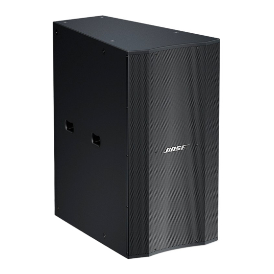
Model MB24 and MB12 Series III Bass
Loudspeakers
Note: For the MB24, ensure that the speaker
under test is in PARALLEL mode for the
following tests. To check the mode the
speaker is set up to operate in, you will need
to remove the eight screws that secure the
input panel assembly in place and verify that
the jumpered connector plugged into the
crossover PCB is in the PARALLEL jack.
Refer to the disassembly procedures in this
service manual for instructions on how to
remove the input panel. This does not apply
to the MB12, as it has only one woofer.
1. Rub and Tick Test
1.1 Apply a 10 Vrms, 10 Hz signal to the
input terminals of the speaker.
Loudspeaker Wiring Diagrams
1+
4-
1-
4+
2+
3-
3+ 2-
1+
4-
1-
4+
2+
3-
3+ 2-
TEST PROCEDURES
1+
1-
2+
2-
3+
3-
4+
4-
®
Model 3202
Series III Wiring Diagram
22
1.2 No extraneous noise such as rubbing,
scraping or ticking should be heard.
2. Phase Test
2.1 Disconnect the connectors at the driver
terminals. Momentarily apply 10 Vdc + 1 Vdc
to the terminals, observing polarity when
connecting the DC power supply. Both of the
drivers should move outward when the DC
level is applied.
3. Frequency Power Sweep Test
3.1 Apply a 10 Vrms, 10 Hz signal to the
speaker input terminals.
3.2 Sweep the input frequency from 10 Hz
to 250 Hz.
3.3 Listen for any buzzes, rattles or other
extraneous noises from the loudspeaker.
Mid 1+
MID-FREQUENCY DRIVERS
Mid 1-
Mid 2+
Mid 2-
To In+
+
3UF/250V
To In-
-
HIGH-FREQUENCY
DRIVER
V2
V2
+
+
-
-
4.5'
4.5'
+
+
-
-
4.5'
4.5'
V2
V2
+
+
-
-
4.5'
4.5'
+
+
-
-
4.5'
4.5'
EAG011-02
C1
C2
6UF/250V
L1
Connector
0.72mH/
5556 2Î11P
1.3mm
OUT
HI-
HI+
HI
+
-
T1.4hp