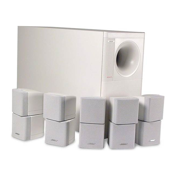
Bose Acoustimass 10 Series I 매뉴얼
{카테고리_이름} Bose Acoustimass 10 Series I에 대한 매뉴얼을 온라인으로 검색하거나 PDF를 다운로드하세요. Bose Acoustimass 10 Series I 17 페이지. Series 2
Bose Acoustimass 10 Series I에 대해서도 마찬가지입니다: 소유자 매뉴얼 (18 페이지), 소유자 매뉴얼 (25 페이지), 소유자 매뉴얼 (17 페이지)

Part number change per supplement 188532-S3 11/2000
Specifications ................................................................................................................................... 2
Figure 1. AM-10 Bass Module ......................................................................................................... 4
Disassembly/Assembly Procedures ........................................................................................... 5-6
Figure 2. Bass Module Exploded View ........................................................................................... 7
Figure 3. Cube Array Exploded View .............................................................................................. 7
Test Procedures ............................................................................................................................ 8-9
Part List Notes ................................................................................................................................ 10
AM-10 Bass Module Part List ........................................................................................................ 11
Figure 4. Bass Module Exploded View .......................................................................................... 11
Crossover Part List ........................................................................................................................ 12
Figure 5. Schematic Diagram REV 01 .......................................................................................... 12
Crossover Mechanical Part List .................................................................................................... 13
Figure 6. Crossover PCB Mechanical Layout ............................................................................... 13
Figure 7. Crossover PCB Etch Layout REV 01 ............................................................................. 13
Cube Array Part List ....................................................................................................................... 14
Figure 8. Cube Array Exploded View ............................................................................................. 14
AM-10 Packaging Part List ............................................................................................................ 15
Figure 9. Packaging Exploded View .............................................................................................. 15
This service manual has been updated with information from supplement 188532-S1.
This affects part numbers for the satellite speaker pivot o-ring, the satellite connectors and the
surround and center channel satellite Twiddlers. These changes resulted in changing the
service manual revision from Rev. 00 to Rev. 01.
This service manual has also been updated with information from supplement 188532-S2.
This affects part numbers for the woofers used in the bass module.
®
Contents
1
