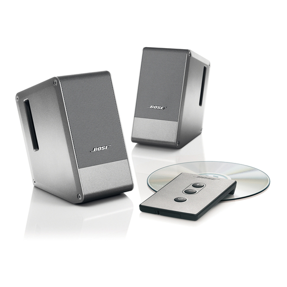
Bose Computer MusicMonitor 서비스 매뉴얼 - 페이지 3
{카테고리_이름} Bose Computer MusicMonitor에 대한 서비스 매뉴얼을 온라인으로 검색하거나 PDF를 다운로드하세요. Bose Computer MusicMonitor 9 페이지. Owner's guide
Bose Computer MusicMonitor에 대해서도 마찬가지입니다: 소유자 매뉴얼 (16 페이지), 소유자 매뉴얼 (25 페이지)

1. Parts that have special safety characteristics are identified by the
or by special notes on the parts list. Use only replacement parts that have critical characteristics
recommended by the manufacturer.
2. Make leakage current or resistance measurements to determine that exposed parts are
acceptably insulated from the supply circuit before returning the unit to the customer.
Use the following checks to perform these measurements:
A. Leakage Current Hot Check-With the unit completely reassembled, plug the AC line cord
directly into a 120V AC outlet. (Do not use an isolation transformer during this test.) Use a leak-
age current tester or a metering system that complies with American National Standards Institute
(ANSI) C101.1 "Leakage Current for Appliances" and Underwriters Laboratories (UL) UL6500 /
UL60065 / IEC 60065 paragraph 9.1.1. With the unit powered on, measure from a known earth
ground (metal water pipe, conduit, etc.) to all exposed metal parts of the unit (antennas, handle
bracket, metal cabinet, screw heads, metallic overlays, control shafts, etc.), especially any
exposed metal parts that offer an electrical return path to the chassis. Any cur-rent measured
must not exceed 0.5 milliamp. Reverse the unit power cord plug in the outlet and repeat test.
ANY MEASUREMENTS NOT WITHIN THE LIMITS SPECIFIED HEREIN INDICATE A POTEN-
TIAL SHOCK HAZARD THAT MUST BE ELIMINATED BEFORE RETURNING THE UNIT TO THE
B. Insulation Resistance Test Cold Check-(1) Unplug the power supply and connect a jumper
wire between the two prongs of the plug. (2) Turn on the power switch of the unit. (3) Measure
the resistance with an ohmmeter between the jumpered AC plug and each exposed metallic
cabinet part on the unit. When testing 3 wire products, the resistance measured to the product
enclosure should be between 2 and infinite MOhms. Also, the resistance measured to exposed
input/output connectors should be between 4 and infinite MOhms. When testing 2 wire products,
the resistance measured to exposed input/output connectors should be between 4 and infinite
MOhms. If it is not within the limits specified, there is the possibility of a shock hazard, and the
unit must be repaired and rechecked before it is returned to the customer.
1. This part is not normally available from Customer Service. Approval from the Field Service
Manager is required before ordering.
2. The individual parts located on the PCBs are listed in the Electrical Part List.
3.
This part is critical for safety purposes. Failure to use a substitute replacement with the
same safety characteristics as the recommended replacement part might create shock, fire
and/or other hazards.
4. This part is referenced for informational purposes only. It is not stocked as a repair part. Refer
to the next higher assembly for a replacement part.
SAFETY INFORMATION
CUSTOMER.
PART LIST NOTES
3
symbol on schematics
