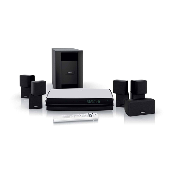
Bose AV28 설치 매뉴얼 - 페이지 5
{카테고리_이름} Bose AV28에 대한 설치 매뉴얼을 온라인으로 검색하거나 PDF를 다운로드하세요. Bose AV28 16 페이지.
Bose AV28에 대해서도 마찬가지입니다: 테스트 절차 (4 페이지)

Figure 2
Front features of media
center
Connecting the antennas
Figure 3
Connections for the AM
and FM antennas
• Place the media center close enough to other sound sources (TV and VCR) to allow for
easy cable connections. If you need additional audio and/or video cables to connect all of
your components, see your dealer or call Bose
address list included with your system.
Front door – Make sure you have
enough room to lift up this door.
The rear panel of the media center provides connections for AM and FM antennas (Figure 3).
Be sure to unwrap the bundled antenna wires and straighten them as much as possible to
ensure the best reception.
Note: Outdoor antennas may be used. To install an outdoor antenna, consult a qualified installer.
Follow all safety instructions supplied with the antenna.
AM antenna
lead
33V
DC POWE R
1.1A
TV
SENSO R
AM
IR
EMITTER
1
OPTICA L
SERIAL
DATA
2
INPU T
SPEAKER
ZONE S
Connecting an FM antenna
Plug the connector on the FM dipole antenna lead into the FM antenna jack. Spread out the
antenna arms. Change the orientation of the antenna arms to get optimum FM reception.
Place the antenna as far from the media center and other components as possible.
Connecting the AM antenna
Note: To mount the AM antenna on a wall, follow the instructions enclosed with the antenna.
1. Plug the connector on the AM antenna lead into the AM antenna jack.
2. Stand the loop antenna on the base. See the instructions enclosed with the AM antenna.
3. Move the AM loop antenna as far as possible, at least 20 inches (50 cm), from the media
center. Experiment with the orientation of the loop for optimum AM reception.
®
customer service. Refer to the Bose
Disc tray – Make sure nothing blocks this tray as it slides
open for you to insert a disc.
FM dipole
antenna lead
RECORD
TAPE
AUX
VC R
T V
VIDEO INPUTS
COMPOSITE
S-VIDEO
L
L
L
L
L
FM
75
ANTENNA
R
R
R
R
R
OPTICA L
DIGI T AL
DIGI T AL
DIGIT AL
DIGI T AL
DIGI T AL
DIGI T AL
OUTPU T
COMPOSITE
S-VIDEO
AUDIO OUTPUTS
AUDIO INPUTS
VIDEO OUTPUTS
System Installation
Display window – Make sure you can view
this information while using your system.
®
5
