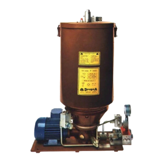
DROPSA 999540 사용자 및 유지보수 매뉴얼 - 페이지 8
{카테고리_이름} DROPSA 999540에 대한 사용자 및 유지보수 매뉴얼을 온라인으로 검색하거나 PDF를 다운로드하세요. DROPSA 999540 15 페이지.

ANOMALY
Irregular flow rate Screw C, which secures
the pump element D and
return spring E, is loose.
9. MAINTENANCE PROCEDURE
Locate the machine in conditions which facilitate easy access.
Utilise individual protection to avoid contact with mineral oil.
Periodic inspections
Periodically it is necessary to check:
VERIFICATION
The state of lubrication
The oil/grease level
Cleanliness of the filling and intake filter (where fitted)
The machine does not require any special tools to carry out checks or maintenance tasks, However, it is
recommended that only tools suitable for the tasks and in good condition should be utilised to avoid injury to persons
or damage to machine parts.
9.1 Assembly/Disassembly
No pump assembly operations are envisaged.
For wall mounting ensure adequate space is available (as shown in the installation diagram) to avoid abnormal
postures and possible impacts; four fixing holes are provided for wall mounting and three for base fitting.
Subsequently it will be necessary, as previously described, to connect the pump to the machine hydraulically and then
to connect the control panel.
During the disassembly phase ensure the tank is empty.
Disconnect the electrical and hydraulic parts.
Where the machine is to be scrapped, do not dispose of potentially polluting parts in the environment, following local
regulations for their correct disposal.
At the time of the machine being scrapped it is necessary to remove and destroy the identification plate and all other
relative documents.
9.2 Regulation
Flow rate (for versions with adjustable flow rates)
It is possible to regulate the flow rate by rotating the regulating screw (8 mm hexagonal key) clockwise to decrease
8
CAUSE
Remove
assembly from the pump body
and completely disassemble it.
To reassemble the pump element
assembly see the sequence in the
diagram.
Check all the parts and reassemble
after having washed them all in
petrol.
Warning: put some Loctite type
sealant on screw C, which is
inserted into pump element D.
Hold the pump element between
wooden vice clamps to prevent
damage to the lapped surface.
REMEDY
the
pump
element
Fixed Pump Element
Part No. 299039 Ø 6 mm
Part No. 299040 Ø 8 mm
WORK CYCLE/RUNNING TIME
1000/every 6 months
2000/once a year
500/every 6 months
Adjustable Pump Element
Part No. 299041 Ø 6 mm
Part No. 299042 Ø 8 mm
