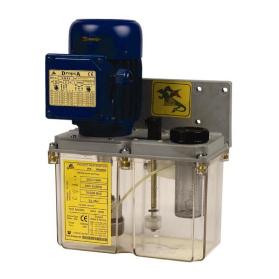
DROPSA Dragon Series 사용자 및 유지보수 매뉴얼 - 페이지 5
{카테고리_이름} DROPSA Dragon Series에 대한 사용자 및 유지보수 매뉴얼을 온라인으로 검색하거나 PDF를 다운로드하세요. DROPSA Dragon Series 12 페이지.
DROPSA Dragon Series에 대해서도 마찬가지입니다: 사용자 운영 및 유지보수 매뉴얼 (13 페이지)

6. UNPACKING AND INSTALLING THE PUMP
6.1 Unpacking
Once a suitable location has been found to install the unit remove the pump from the packaging. Check the pump has
not been damaged during transportation or storage. No particular disposal procedures are necessary, however
packing should be disposed of in accordance with regulations that may be in force in your area or state.
6.2 Installing the pump
In order to facilitate any maintenance intervention, to avoid unnatural posture for personnel during machine
operation or the possibility of sustaining impacts, install the machine in a comfortable and easy-to-reach location.
Allow sufficient space for the installation.
Do not install the unit in aggressive or explosive/inflammable environments or on vibrating surfaces.
7. INSTRUCTIONS FOR USE
7.1 Installing the pump
Damage to the power supply cable or the housing may result in contact with the high-voltage live elements and
therefore the danger of death:
Check that the power supply cable and the unit itself are undamaged before use.
In the event that either the power supply cable or the unit itself is damaged, do not turn on the device!
If the power supply cable is damaged, replace it with a new one.
The unit may be opened and repaired only by specialised personnel.
In order to avoid the danger of fulguration due to direct or indirect contacts with the live parts, it is necessary
that the electric power supply line be adequately protected by a special magnetothermal differential switch
with a cut-off threshold of 0.03 Ampere and a maximum cut-off time of 1 second.
The cut-off power of the switch must be 10 kA and the rated current In = 4 A.
The connection of the manostat directly attached to the tank must be effectuated at 24 V ac/dc.
The pump must not be used while submerged in fluids or in particularly aggressive or explosive/inflammable
settings, unless specially preset by the supplier for such purposes.
For correct fastening, check the dimensions of the axle bases reported in the illustrations.
Use gloves and safety goggles, as stipulated in the safety chart for the lubricating oil.
DO NOT use lubricants that may irritate the NBR gaskets; if in doubt, contact the Dropsa SpA technical office,
which can provide you with a detailed chart of recommended oils.
Do not ignore dangers to the health and maintain the regular hygiene standards.
Attention! All the electrical components must be grounded. This applies both to the electrical components
themselves and the control devices. To this end, ensure that the grounding wire is correctly connected. For
safety reasons, the grounding conductor must be approx. 100 mm longer than the phase conductors. In the
event of an accidental disconnection of the cable, the grounding terminal must be the last to detach itself.
Steps to be taken before starting up the device:
Check that the pump is in good condition;
Fill the tank with an appropriate lubricant (the min/max indications are on the tank);
Check that the pump is at running temperature and that the tubes are free of air bubbles;
Check that the electrical connection has been carried out correctly (CEI 64/8, IEC 364);
Check the connection of the level (and, if present, the manostat) to the control board;
With the pump activated, check the direction of rotation of the electric motor; if the motor turns the wrong
way, it is necessary to invert the connection of the cables.
The minimum level condition is supplied, unless requested differently by the client, with the contact closed for the
minimum level. Should the user require a contact that is normally open, it is necessary (with the tank open) to invert
the operating direction of the float.
The pressure only can be modified. To change the set value it's needed turn clockwise (increase)or counterclockwise
(decrease) the adjustment screw of the by-pass valve mounted on the fixing plate.
5
