DROPSA Dragon Series 사용자 운영 및 유지보수 매뉴얼 - 페이지 5
{카테고리_이름} DROPSA Dragon Series에 대한 사용자 운영 및 유지보수 매뉴얼을 온라인으로 검색하거나 PDF를 다운로드하세요. DROPSA Dragon Series 13 페이지.
DROPSA Dragon Series에 대해서도 마찬가지입니다: 사용자 및 유지보수 매뉴얼 (12 페이지)

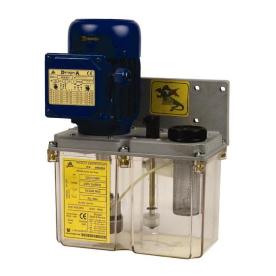
5. COMPONENTS
PUMP COMPONENTS
1
Motor
2
Connector
3
Pump
Level indicator (optical in
4
floating
the picture –
switch
optional)
5
Filter
6
Tank
7
Distributor block
Non-return valve
8
(optional)
9
By-pass adjustment screw
10
Clamping bracket
11
Pressure switch (optional)
12
Pressure gauge
13
Plug
6. UNPACKING AND INSTALLATION
6.1 UNPACKING
Once the suitable location for installation has been identified, open the package and remove the pump. Check that it was not
damaged during transport or storage. The packaging material does not require special disposal precautions as it is not in any
way dangerous or polluting. Refer to the local regulations for disposal.
6.2 INSTALLATION
Pump assembly operations are not required.
Allow a sufficient amount of space for installation, leaving a minimum perimetric space of 100 mm (3,93 in.).
For wall-mounting, suitable space must be provided (see the installation diagram) to prevent abnormal positions or the
possibility of impacts; fixing holes are provided on the plate (see Para. 12).
Then, the pump must be connected hydraulically to the machine. Make the connection to the control panel and fill the tank
(making sure not to exceed the maximum visual level).
Empty the tank during the disassembly phase.
Disconnect the electric part from the hydraulic part.
1
2
3
13
12
11
10
8
6
5
4
5
