Anritsu Company VectorStar ME7848A-0240 빠른 시작 매뉴얼 - 페이지 10
{카테고리_이름} Anritsu Company VectorStar ME7848A-0240에 대한 빠른 시작 매뉴얼을 온라인으로 검색하거나 PDF를 다운로드하세요. Anritsu Company VectorStar ME7848A-0240 15 페이지. Opto-electronic network analyzer systems
Anritsu Company VectorStar ME7848A-0240에 대해서도 마찬가지입니다: 빠른 시작 매뉴얼 (17 페이지)

4. Making Opto-electronic Component Measurements
3. The response is the absolute detected power and will have a similar shape to the |S21| plots in the
previous section but the numerical levels will be different.
Figure 3.
Example Plot of the Functional Test at +5 and +2 dBm Optical Power Levels
An example plot of the functional test is shown in
power (blue curve) and +2 dBm optical power (for reference, red curve). The -0271/0272 and -0240 systems will
have values somewhat lower than the red curve (2-5 dB for the -0271/0272 and 5-10 dB lower for the -0240).
4.
Making Opto-electronic Component Measurements
The typical measurement scenario with the ME7848A opto-electronic network analyzer system is to analyze
the conversion behavior of E/O or O/E devices or to study the RF envelope behavior for signals passing through
O/O components. All of these measurements are done from an RF perspective by the VNA with the optical
carrier (provided by the laser) acting as a parameter. Much more measurement information is available in the
VectorStar Calibration and Measurement Guide, 10410-00318, (with an entire chapter devoted to this
particular measurement class) but some salient points will be summarized here.
• The VNA calibration establishes reference planes (for insertion loss and phase, group delay, and
reflection) at the ends of the RF cables (or wherever the calibration was performed). Thus a
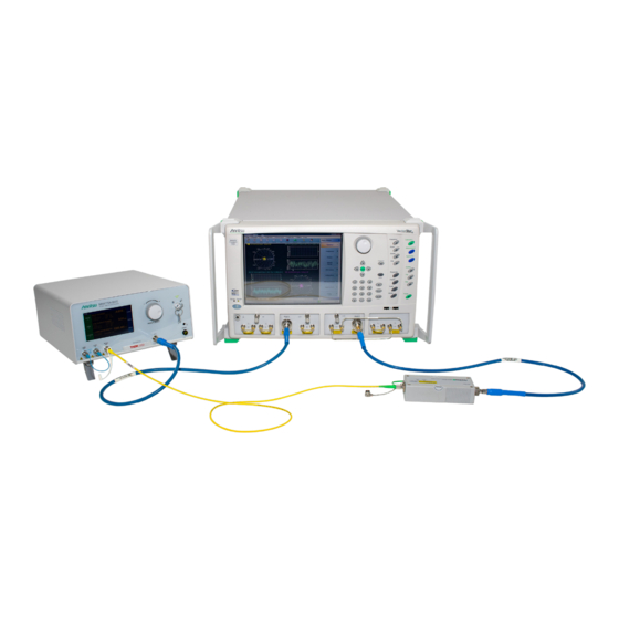
measurement of, for example insertion loss, the structure in
conversion loss of the E/O and O/E modules and the optical interconnect.
QSG-10
Figure 3
for the ME7848A-0270 system at +5 dBm optical
PN: 10410-00777 Rev. B
Figure 2
will represent the combined
ME7848A QSG
