Ansa RS-1 설치 및 운영 지침 매뉴얼 - 페이지 8
{카테고리_이름} Ansa RS-1에 대한 설치 및 운영 지침 매뉴얼을 온라인으로 검색하거나 PDF를 다운로드하세요. Ansa RS-1 12 페이지. Ansa roller door remote control unit

- 1. Table of Contents
- 2. General Description
- 3. General Operation
- 4. Multi Channel Keyfobs
- 5. Fitting the RS-1 Control Unit
- 6. Electrical Connections
- 7. Photoelectric Cell Safety System (Optional)
- 8. Light Grid Safety System (Optional)
- 9. Alarm System (Optional)
- 9. Figure 16
- 9. Commissioning
- 9. Adding/Deleting Transmitters & Wireless Access Controls
- 9. Dip Switch Options & Special Settings
- 9. Technical Specifications
8
Alarm System - Type AL-12 H/W (optional)
9.1 Function
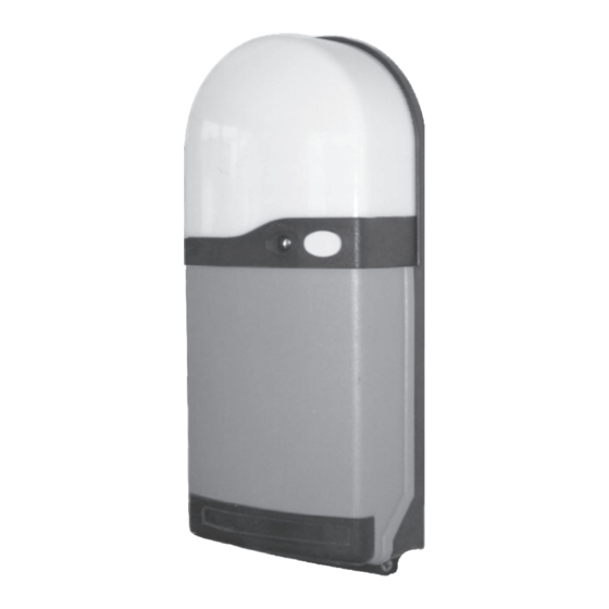
The AL-12 H/W System is an intruder alarm designed to protect an attempted break in through the garage door. The system
automatically arms when the door is closed and is automatically disarmed whenever the door is opened using the keyfob transmitters
or other access controls. The alarm module is fitted with a 90db siren and alarm status indicator. The alarm module is also equipped
with volt free terminals which provide the option to connect the system direct to the main house alarm. The system uses a sealed
magnetic switch and magnet to trigger the alarm if an attempt is made to force the door open.
Alarm Module
Optional
wiring
connection
to house
alarm
system
Alarm Status LED
Alarm cable plug
and PCB socket
8.2 Installation
Fitting the alarm module
·
Fix the Alarm Module to th left of the RS-1 Control Unit using the plugs and screws provided. Pass the connection lead and plug
through the right hand cable gland entry and route the cable as shown away from the radio receiver tile and connect the plug to the
alarm socket on the RS1 circuit board. NOTE - Do not fit the Alarm module next to the Radio receiver tile.
Fit the Alarm Magnet
·
Operate the motor override and position the door at shoulder height. Fit the alarm magnet to the bottom rail using the self drill/self
tapping screws provided and leave a 10mm gap to the door guide (as shown in figure 16).
Fit the Alarm Trip Switch
·
Fit the alarm trip switch 'horizontally' as shown to the door guide channel (can be fitted to either guide channel) using the self adhesive
pad supplied. Route the 2 core connection lead neatly and connect to the RS1 control unit as shown in figure 9a. and neatly connect the
wires to the RS1 terminals AL1 and AL2.
Self adhesive fittings & nail clips are provided to secure the alarm module & trip switch cables to the door guide and opening structure.
8.3 Operation
The unit automatically arms on closure. A 'break in' alarm signal is transmitted if the bottom rail is forced open due to interruption of
the magnet and transmitter. Note the alarm automatically resets 15 minutes after it is activated.
8.4 Testing
Wait at least 1 minute after the door closes for the system to arm. Use the manual override to raise the door slightly. The alarm should
activate (90 DB sounder). Operate the keyfob to switch off the alarm.
8.5 Alarm LED Status Indication
Green ON
Red ON
Red / Green Flashing - Door is opening or closing or is part open
8.6 Optional connection to main house alarm system
The ANSA AL-12 Modular is equipped with volt free normally closed terminals for optional direct connection to the main house
alarm system. A break in attempt will cause the ANSA alarm and house alarm to activate simultaneously.
Page 7
Leave a 10mm gap from the magnet to the door guide
- Door is closed and Alarm system is SET
- Door is open and Alarm system is OFF
RS1 Unit
Door
guide
Radio
receiver
tile
Alarm
trip
switch
Figure 16
Alarm system general layout diagram
Magnet
Bottom
rail
