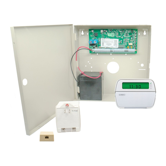
DSC PowerSeries PC1832 설치 매뉴얼 - 페이지 4
{카테고리_이름} DSC PowerSeries PC1832에 대한 설치 매뉴얼을 온라인으로 검색하거나 PDF를 다운로드하세요. DSC PowerSeries PC1832 13 페이지. System
enhancement
module
DSC PowerSeries PC1832에 대해서도 마찬가지입니다: 설치 매뉴얼 (17 페이지), 설치 매뉴얼 (20 페이지), 매뉴얼 (18 페이지)

Keybus Wiring
The 4-wire KEYBUS (red, black, yellow and green) is the communication connection between the control panel and all modules. The 4 KEYBUS terminals of all
modules must be connected to the 4 KEYBUS terminals of the main control panel.
The following rules must be followed when wiring the Keybus:
• Minimum 22 AWG wire, max. 18 AWG (2-wire twisted preferred)
• Do not use shielded wire
• Modules can be home run, connected in series or T-tapped, provided that the maximum wire distance from
the control panel to any module does not exceed 1,000 feet (305m)
• No more than 3,000 feet (915m) of wire can be used in total
Zone Wiring
Zones can be wired for Normally Open or Normally Closed contacts, with Single-End-of-Line (SEOL) or
Double End-of-Line (DEOL) resistors. Observe the following guidelines:
• For UL Listed Installations use SEOL or DEOL only
• Minimum 22 AWG wire, maximum 18 AWG
• Do not use shielded wire
•
Wire run resistance shall not exceed 100
Wire Gauge
22
20
19
18
Figures are based on maximum wiring resistance of 100Ω
• [001]-[004] Selects Zone Definition
• [013] Opt [1] Selects Normally Closed or EOL resistors
• [013] Opt [2] Selects SEOL or DEOL resistors
• [101]-[108] Opt [14], [15], [16] Selects Normally Closed SEOL or DEOL for on-board zones
(PC1832/1864, Zone 1-8; PC1616, Zones 1-6)
Zone Status - Loop Resistance/Loop Status
• Fault - 0Ω (shorted wire/loop)
• Secure - 5600Ω (contact closed)
Zone Expanders
Zone expanders add zones in groups of eight to the
Alarm system. Module jumpers J1, J2, J3 are
required to assign zones to these modules. Jumper
settings for PC5108 v2 are shown here.
PC5108 1.0 supports first 32 zones only
PC5700 enrolls as two modules
Do NOT use PC5108 v1 and PC5108 v2 on the
same panel.
Bell Wiring
These terminals supply 700mA of current at 12VDC for commercial installations and 11.1-12.6VDC for residential installations (e.g.,
DSC SD-15 WULF). To comply with NFPA 72 Temporal Three Pattern requirements, Program [013] Opt [8] must be ON. Note that
Steady, Pulsed alarms are also supported.
The Bell output is supervised and power limited by 2A PTC. If unused, connect a 1000Ω resistor across Bell+ and Bell- to prevent the
panel from displaying a trouble. See [*][2].
PowerSeries PC1616/PC1832/PC1864 Installation Guide
Ω.
Refer to the chart below
Burglary Zone Wiring Chart
Maximum Wire length to end-of-line
resistor (ft/meters)
3000/914
4900/1493
6200/1889
7800/2377
• Tamper - infinite (broken wire, open)
• Violated - 11,200Ω (contact open)
Module Jumpers
J1
J2
ON
ON
OFF
ON
ON
OFF
OFF
OFF
ON
ON
OFF
ON
ON
OFF
OFF
OFF
:
Zones Assigned
J3
ON
Zones Disabled
ON
Zones 09-16
ON
Zones 17-24
ON
Zones 25-32
OFF
Zones 33-40
OFF
Zones 41-48
OFF
Zones 49-56
Refer to the associated installation sheet for jumper locations for the
PC5108 v1 and PC5700.
OFF
Zones 57-64
- 4 -
150' (46m)
150' (46m)
CONTROL
PANEL
500' (152m)
Normally Closed Loops - Do NOT use for UL Installations
Single End-of-Line Resistor Wiring
Double End-of-Line Resistor Wiring
500' (152m)
BELL/SIREN
700mA (max.)
OBSERVE
POLARITY
