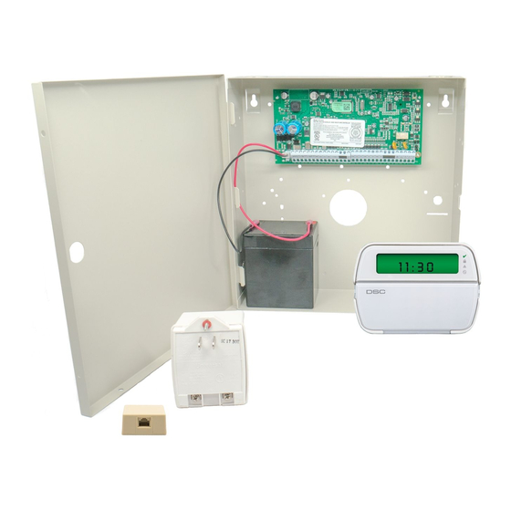
DSC PowerSeries PC1864 설치 매뉴얼 - 페이지 8
{카테고리_이름} DSC PowerSeries PC1864에 대한 설치 매뉴얼을 온라인으로 검색하거나 PDF를 다운로드하세요. DSC PowerSeries PC1864 20 페이지. System
enhancement
module
DSC PowerSeries PC1864에 대해서도 마찬가지입니다: 설치 매뉴얼 (17 페이지), 설치 매뉴얼 (13 페이지), 매뉴얼 (18 페이지)

STEP 5: WIRE THE SEM TO THE PANEL
Verify panel AC power is removed and
the backup battery is disconnected.
SEM
+12V
YELLOW (IN)
GREEN (OUT)
GND
•
Connect panel terminal SEM GND to BLK.
•
Connect panel terminal
•
Connect panel terminal
•
Use the included red cable with the two prong battery connector
to connect the battery to both the SEM and the panel. For a power-
limited circuit, ensure the fuse is inside the PowerSeries panel.
Once wiring is complete, route the antenna(s) outside of the enclosure,
away from the SEM, and replace the enclosure cover. Please note that
the antenna(s) should be routed through the second and third channel
openings at the top of the enclosure (see below).
CDMA/HSPA
Modules
8
YELLOW (IN)
to YEL.
GREEN (OUT)
to GRN.
LTE Modules
12V Battery
RED
BLK
YEL
GRN
PowerSeries Panel
