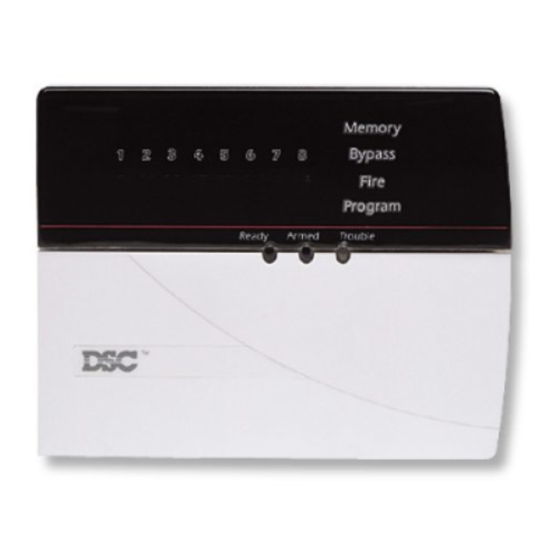
DSC PC5700 설치 지침
{카테고리_이름} DSC PC5700에 대한 설치 지침을 온라인으로 검색하거나 PDF를 다운로드하세요. DSC PC5700 2 페이지. Fire module
DSC PC5700에 대해서도 마찬가지입니다: 설치 지침 (2 페이지)

The PC5700 is a zone expansion module to be used with any control panel which supports the PC5108 module. In addition to four general
purpose zone inputs, the module provides the following features: two Class A supervisory waterflow zones, ground fault detection and dual-
supervised telephone lines. The PC5700 connects to a control panel via the 4-wire Keybus using standard 22-gauge unshielded cable.
PC5700 Connection Diagram
For Commercial Fire installations, please refer to Section 6 of the PC5020/PC5020CF Installation Manual.
Zone 7 and Zone 8 do not need to be wired and can be programmed as null (00) if the control panel used has a software
version of 3.1 or higher.
When installing the PC5700 fire module, ensure that a minimum 1/4" (6.4mm) separation is maintained at all points
between power limited and all other non-power limited wiring and connections.
WARNING: A maximum of 100V RMS may be present on telephone connections. Disconnect prior to servicing.
Jumpers J1-J6
Jumpers are used to determine which zones will be assigned to
the PC5700. Jumpers J1-J3 control the first four PC5700 zones.
Jumpers J4-J6 control the second four PC5700 zones (two
water-flow, ground fault and TLM fault zones).
Jumper Settings
The PC5700 module can be used to add up to 6 additional
hardwired zones to the control panel.
WARNING
Please refer to the System Installation Manual for
information on limitations regarding product use and function and
information on the limitations as to liability of the manufacturer.
Installation Instructions
Zone Inputs
The first four zone inputs (Z1-Z4) on the PC5700 are general
purpose zones which can be programmed as any zone type
offered by the alarm control panel.
The last four zone inputs are as follows:
Zone #
Zone Type
Zone 5
Class A (waterflow)
Zone 6
Class A (waterflow)
Zone 7
Ground fault
detection zone
Zone 8
TLM fault
The zone definitions for these four zones should be as follows:
Zone 5
[07] Delayed Fire or [08] Standard Fire
Zone 6
[07] Delayed Fire or [08] Standard Fire
Zone 7
[08] Standard Fire
Zone 8
[09] 24Hr Supervisory (LINKS)
For control panels v3.x and higher, please refer to the jumper
settings below:
Expander Zones
Group A (Zones 1-8)
J1
Group B (Not used)
ON
OFF
ON
OFF
ON
OFF
ON
OFF
On control panels with software versions 3.x and higher,
the PC5700 v2.0 will operate in a single group of 8 zones.
Terminals
A1+, A1–, B1+,B1 circuit 1
A2+, A2–, B2+,B2 circuit 2
EGND
TIP2, RNG2, TIP1, RNG1
Jumpers
System Zones
J2
J3
Assigned
ON
ON
Zones Disabled
ON
ON
Zones 9 - 16
OFF
ON
Zones 17 - 24
OFF
ON
Zones 25 - 32
ON
OFF
Zones 33 - 40
ON
OFF
Zones 41 - 48
OFF
OFF
Zones 49 - 56
OFF
OFF
Zones 57 - 64
PC57OO
Fire Module v2.O
