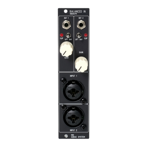
ADDAC System ADDAC711 조립 설명서 - 페이지 5
{카테고리_이름} ADDAC System ADDAC711에 대한 조립 설명서을 온라인으로 검색하거나 PDF를 다운로드하세요. ADDAC System ADDAC711 9 페이지. Balanced outputs

ADDAC711 Assembly Guide
STEP 5:
Place and solder the transformers, notice there's one leg which is placed at an odd spacing which
defines the orientation of the part.
STEP 6:
Next we'll need to prepare some parts before placing them to the front panel.
One of the pots need 2 legs to be cutted before placing, shown below.
! NOTICE ! Just one of the potentiometers need this modification
STEP 7:
Locate the jacks and cut the thinest leg like shown below.
ADDAC SYSTEM
page 5
