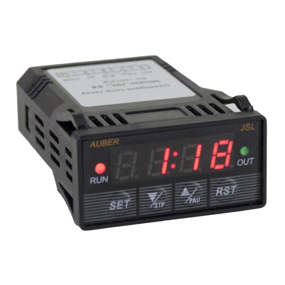
Auber Instruments JSL-64A 사용 설명서
{카테고리_이름} Auber Instruments JSL-64A에 대한 사용 설명서을 온라인으로 검색하거나 PDF를 다운로드하세요. Auber Instruments JSL-64A 5 페이지. 1/32 din general purpose timer

AUBER INSTRUMENTS
Instruction Manual
1.
Overview
This JSL-64 timer can count from 0.01 second to 9999 minutes. Operating
function modes include single delay, double delay, and cycle delay. It can
count-down or count-up. The timer can be activated automatically when
powering up, by front key pad, or via remote switch.
2. Specification
Timer range: 0.01 second to 9999 minutes.
Timer mode: single delay, double delay, cycle delay, count-up timer.
Timer trigger: power on, front key pad, or remote switch.
Timer error: < 1 s/day.
Power supply: 85 - 260 V AC or DC.
Power consumption: < 2 W.
Relay output: 10A at 240 VAC / 30 VDC (resistive load)
Average relay life: 100,000 times at rated current.
Operating temperature: 0 - 60° C.
Humidity: 0 - 95% RH.
Panel cutout: 22 x 45 mm.
Outer dimension: 24 x 48 x 75 mm (1" x 2" x 3").
3. Front Panel
4
5
Figure1. Front panel.
1. Time unit indicator (colon sign): Turns on when time format is MM:SS
(Minutes: Seconds) or HH:MM (Hours: Minutes) and flashes when the timer is
running; turns off when time unit is M (Minutes) or S (Seconds).
2. LED digital display: During normal operation as a timer, it displays the actual
time. When timer is stopped, it displays the preset value. During controller
setup, it displays parameter value.
3. OUT indicator: Turns on when relay is on; turns off when relay is off.
4. RUN indicator: Turns on when timer is running; blinking/flashing when timer
is paused; turns off when timer is stopped.
5. SET key: press it once to set timer and relay delay timer T1/T2 (if applicable.
T1 timer shows as t-1, T2 timer shows as t-2); press and hold it for 3 second
will enter the programming mode. This key is disabled when timer is running.
2021.03
JSL-64A 1/32 DIN General Purpose Timer
6
7
8
Version 1.2 (March 2021)
6. DOWN key / STP key: Reduces the value in the programming mode; when
the timer is running, press it to stop the timer. (For special stop function in
single delayed on mode, please see note 6 on page 3 for details).
7. UP key / PAU key: Increases the value in the programming mode; when
timer is running, press and hold it will pause the timer; the timer will continue
running after this key is released.
8. RST key: Reset key. When the timer is running, press it will restart the timer.
If "RUN" parameter is set to RST, press it will start the timer after powered up.
4. Terminal Assignment
1
Pin #
Function
Note: pin 1 to pin 5 are high voltage pins.
2
1
AC power input
3
2
AC power input
3
N.C.
4
Relay Output
5
Relay Output
Note: pin 6 to pin 10 are low voltage pins.
6
Reset
7
Pause
8
Stop
Special
9
Terminal
10
Common
Note A. Terminal 4 and 5 are for normally-open (NO) relay output. When this
relay is energized (or when the OUT LED is on), pin 4 is connected to pin 5
internally; When the relay is NOT energized (or when the OUT LED is off), pin
4 is disconnected from pin 5. The relay is a "dry switch" that does not provide
power by itself. Please see the wiring examples in Section 7.
WWW.AUBERINS.COM
Figure 2. Terminal assignment.
Description
85V ~ 260V AC power input.
Not connected.
Normally open (NO) relay. The relay
action is in synchronize with the OUT
indicator.
When connected with COM pin,
works as the RST key to reset the
timer.
When connected with COM pin,
works as the PAU key to pause the
timer.
When connected with COM pin,
works as the STP key to stop the
timer.
Special terminal reserved for
Espresso Shot Timer (EST) function.
Common pin.
Note
A
B
B
B
C
B
P1/5
