3onedata SW4485I 빠른 설치 매뉴얼 - 페이지 2
{카테고리_이름} 3onedata SW4485I에 대한 빠른 설치 매뉴얼을 온라인으로 검색하거나 PDF를 다운로드하세요. 3onedata SW4485I 3 페이지.
3onedata SW4485I에 대해서도 마찬가지입니다: 사용자 설명서 (3 페이지)
Step 1
Check if the DIN-Rail mounting kit is installed firmly.
Step 2
Insert the bottom of DIN-Rail mounting kit (one side
with spring support) into DIN-Rail, and then insert
the top into DIN-Rail.
Tips:
Insert a little to the bottom, lift upward and then insert
to the top.
Step 3
Check and confirm the product is firmly installed on
DIN-Rail, then mounting ends.
【Disassembling DIN-Rail】
Step 1
Device power off.
Step 2
After lift the device upward slightly, first shift out the
top of DIN-Rail mounting kit, and then shift out the
bottom of DIN-Rail, disassembling ends.
Notice before power on:
Power ON operation: First insert the power supply
terminal block into the device power supply interface,
and then plug the power supply plug contact and power
on.
Power OFF operation: First, remove the power plug,
and then remove the wiring section of terminal block.
Please pay attention to the above operation sequence.
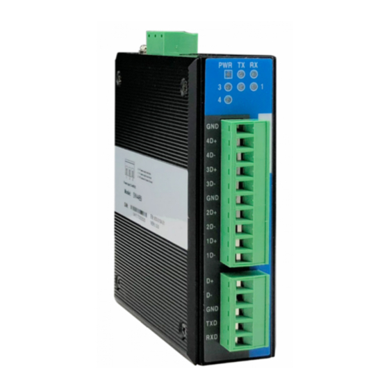
【Power Supply Connection】
The product provides 3-pin 7.62mm pitch
terminal blocks, in which 1 and 3 are power
input and 2 is grounding. The power supply has the function of
non-polarity and anti-reverse connection, and the device can
still work normally after the reverse connection.
Voltage range: 12VDC~48VDC.
【Serial Port Connection】
Lower device RS-485
The device provides 4 RS-485
lower device interfaces, the
interface
5.08mm pitch terminal block, support 15kV electrostatic
protection, 2kVAC isolation protection. The pin definitions as
shown in the follow table:
PIN
Definition
Note
1.
GND
Signal ground
2.
4D+
RS-485 positive signal input
(out) terminal
3.
4D-
RS-485 negative signal input
(out) terminal
4.
3D+
RS-485 positive signal input
(out) terminal
5.
3D-
RS-485 negative signal input
(out) terminal
6.
GND
Signal ground
7.
2D+
RS-485 positive signal input
(out) terminal
8.
2D-
RS-485 negative signal input
(out) terminal
9.
1D+
RS-485 positive signal input
(out) terminal
10.
1D-
RS-485 negative signal input
(out) terminal
RS-232/485 serial port of the upper device
The device provides 1 RS-232/485 upper
device port, the interface form is 5-pin
5.08mm pitch terminal block, supports 15kV electrostatic
protection, 2kVAC isolation protection. The pin definitions as
shown in the follow table:
PIN
Definition
1.
D+
2.
D-
3.
GND
4.
TxD
5.
RxD
type
is
10-pin
【Checking LED Indicator】
The device provides LED indicators to monitor the device
working status with a comprehensive simplified
troubleshooting; the function of each LED is described in the
table as below:
LED
Indicate
ON
PWR
OFF
ON
Blinking
1-4
OFF
Blinking
TX
OFF
Blinking
RX
OFF
Note
RS-485 positive signal input (out)
RS-485 negative signal input
RS-232 signal ground wire
RS-232 data sending terminal
RS-232 data receiving terminal
Description
PWR is connected and running
normally
PWR is disconnected and running
abnormally
The device is normally powered on,
and the corresponding interface
from D1 ~ D4 is in the state of
receiving/sending data
D1~D4 corresponding interfaces
are sending/receiving data
Fault warning: the device is not
powered on or the device is
normally powered on, D1~D4
corresponding interface signal line
is inversely connected
transmitting data
No data transmission
receiving data
No data receiving