3onedata NP5100-2T-32DI 빠른 설치 매뉴얼 - 페이지 3
{카테고리_이름} 3onedata NP5100-2T-32DI에 대한 빠른 설치 매뉴얼을 온라인으로 검색하거나 PDF를 다운로드하세요. 3onedata NP5100-2T-32DI 4 페이지.

In case of damaging TF card, user needs to power off
the device first to change the TF card.
【Set OLED Display】
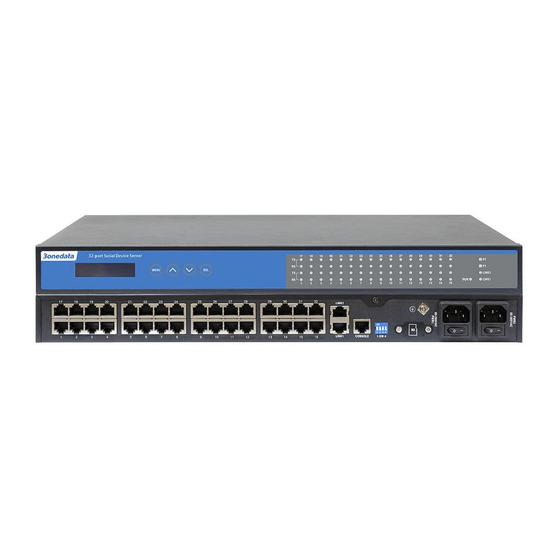
Model I and model III of the device provide liquid crystal
display screens. Under normal working conditions, the liquid
crystal display is dark and shows the IP address of LAN1.
User can press the button to change the settings and query
accordingly:
Key
Name
Command
MENU
Menu/Exit
Enter Main Menu/Back
Page UP
Select the last target
︿
Page Down
Select the next target
﹀
SEL
Select/confirm
Select selected item
Display resolution is 128*16, support numbers, English case, ".
", "-", "_", "↑", "↓" and other characters, support single line left
and right scroll. Supports cursor blinking to determine the
current cursor position. Trigger the button, the screen light is
on. If there is no new operation for 30s, the screen would go
into sleep state.
Detailed operation steps of OLED display screen are as
follows:
Step 1
Start up, the first line shows the device name, the
second line shows the LAN1 IP address.
Device Server
192.168.001.254
Step 2
Trigger the MENU key to enter the menu interface,
options:
Main menu
Server setting
Server setting: basic information of the device,
-
please skip to step 3 and step 6 for this
setting;
Network
setting:
-
please skip to step 5 and step 6 for this
setting;
Step 3
Step 4
Step 5
network
configuration,
Save/Restart: restart the device, skip to step 6
-
for this setting.
Select Server setting on the Menu interface, trigger
SEL key, enter the configuration interface of Server
setting, options:
Server setting
Serial number
Serial number (read only);
-
Server name (read only);
-
Firmware ver (read only);
-
Model name (read only);
-
Select Network setting on the Menu interface,
trigger SEL key, enter the configuration interface of
Network setting, options:
Network setting
LAN mode
LAN mode: network port mode, which
-
supports single IP and dual IP configuration;
Mode config: single IP mode configuration,
-
supporting Redundancy mode and Exchange
mode configuration;
LAN 1: network card 1 configuration
-
LAN 2: network card 2 configuration
-
Note:
"Mode config" and "LAN 1" should be configured when
"LAN mode" is "Single IP". "LAN1" and "LAN 2"
should be configured when "LAN mode" is "Dual IP".
Select LAN 1(LAN 2) on the Network setting
interface, trigger SEL key, enter the configuration
interface of LAN 1(LAN 2), options:
LAN 1
Ethernet status
Ethernet status: network card state (read
-
only);
MAC address: MAC address (read only);
-
IP config: IP configuration method (trigger
-
SEL key configuration)
Options: STATIC, DHCP, BOOTP;
IP address (read-write);
-
Netmask (read-write);
-
Gateway: default gateway (read-write).
-
Note:
When the configuration needs to be modified, it can be
triggered by ∧ and ∨ keys to change the value.
Step 6
Select Save/Restart on the Menu interface, trigger
SEL key, enter the configuration interface of
Save/Restart, options:
Save/Restart
Restart
Restart: reboot the device.
-
Notice:
Select Restart, and the interface first displays the
Disable option (prevent pressing the key too long and
misoperation), which can trigger the ﹀ key, select the
Enable option, and then trigger the SEL key to restart
the device.
【Checking LED Indicator】
The series products provide LED indicators to monitor the
device working status with a comprehensive simplified
troubleshooting; the function of each LED is described in the
table as below:
LED
Indicate
Description
PWR is connected and running
ON
normally
POWER
(1-2)
PWR is disconnected and
OFF
running abnormally
Blinking
The system is running normally
The system is not running or
RUN
OFF
running abnormally
ON
System is running abnormally
