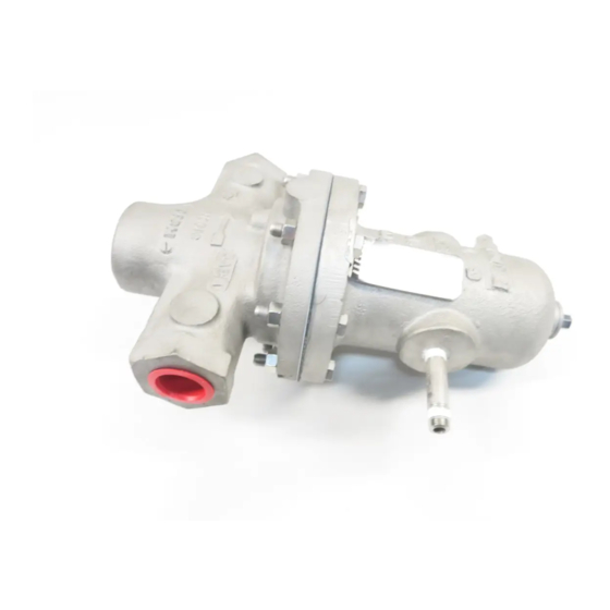
cashco DA2 설치, 운영 및 유지보수 매뉴얼 - 페이지 11
{카테고리_이름} cashco DA2에 대한 설치, 운영 및 유지보수 매뉴얼을 온라인으로 검색하거나 PDF를 다운로드하세요. cashco DA2 16 페이지. Direct-acting, positive bias differential pressure reducing regulator

of valve plug (20). Hold torque wrench
sta tion ary and rotate diaphragm lock nut
(7) to the following torque values:
Body Size
in
(DN)
1/2" - 1"
(15-25)
1 1/4" - 2" (32-50)
2 1/2" - 4" (65-100)
DO NOT allow valve plug (20) to rotate
against seat ring (21) during tightening.
i.
This completes ITA reassembly.
8. Units with V-TFE & CTFE seat ring (21): Due
to the relative "hardness" of the V-TFE & CTFE
ma te ri al, to obtain the best possible shutoff it
is nec es sary to "coin" the V-TFE & CTFE with
a per ma nent in den ta tion.
a. Close-off the outlet connection.
b. The level of seat leakage can be quantified
at the internal sens ing drilled plug (32) for
internal sensing units. For external sensing
units, it will be nec es sary to re move the
in ter nal sensing plug (33).
c. Pressurize the valve's inlet with gas or air
to 50 - 150 psig (3.5 - 10 Barg).
d. Using a soft-headed mallet (rubber,
leath er), sharply rap the top end of the
plug (20) for composition di a phragm de-
signs, or the pis ton-guide bear ing (13) for
metal di a phragm designs. (NOTE: Gas
will escape as the plug (20) opens at the
seat ring (21). Allow sufficient time for
leak age pressure on out let to bleed-off.)
The hammer rap should be strong enough
to "bounce" the plug (20) into the seat
ring (21), leaving the "coined" in den ta tion.
Check for leakage at the internal sensing
port with a leak detection fluid. One bubble
per second is typical of Class IV shut off.
e. Repeat d. a minimum of 2 times until the
best possible seat leakage is ob tained.
f.
After "coining" completed, remove gas
pressure source, remove outlet clo sure,
and re in stall plug (33) if removed.
9. Metal Diaphragm Designs:
a. Install new diaphragm gasket (37) onto
body (23) diaphragm flange.
b. Position diaphragm(s) (9) onto body's (23)
diaphragm flange.
c. Position upper diaphragm pressure plate
(8) onto center top of diaphragm(s)) (9)
with counterbore upwards.
IOM-DA2
Torque
ft-lbs
(N-m)
60-70
(81-95)
120-130
(163-176)
180-200
(244-271)
10. Lubricate and install o-rings (34) into grooves
on the adjusting screw (1).
11. Assembly of range spring and spring chamber:
a. Lubricate the threads of adjusting screw
(1) then thread into the spring follower (5).
The spring follower should be threaded
up adjusting the screw to within 3/8" of
the top threads (see sectional drawing,
figure 5.
b. Insert adjusting screw-spring follower into
spring chamber (4). NOTE: Milled slots in
spring follower must align with ribs in the
bore of the spring chamber. The top of
the adjusting screw must fit in the center
hole of spring chamber. A light rap with
a wooden handle of a hammer may be
needed to fully install the adjusting screw
into the spring chamber.
c. Aligning match marks and bolt holes,
place spring chamber (4) over range
spring (6.1).
flange reaches the body flange without
a gap, turn adjusting screw (1) CW 2-3
turns. Repeat this procedure until the
flanges are approximately 1/8" apart.
Be sure that range spring is properly
seated into counterbore on spring follower.
NOTE: For metal diaphragm con struc tion,
if flang es do not come to geth er equal ly,
the upper di a phragm pres sure plate (8)
may be off-center. Remove spring cham-
ber (4) and reposition upper di a phragm
pres sure plate (8) until the spring chamber
(4) comes down evenly on all sides.
12. Reinstall all flange bolts (11) and nuts (12)
with nameplate (99) located under one bolt
head. Hand-tighten nuts (12).
NOTE: If a three-ply diaphragm is being used,
it is important that the diaphragm (9) is "pre-
formed" – allow formation of a diaphragm (9)
convolution. Starting with the body bolts and
nuts (11,12) hand tight ened, "preforming" can
be accomplished by any one of the following
techniques:
a. Relax range spring fully by rotating
ad just ing screw CCW.
b. Apply 30 psig (2.1 Barg) pressure to the
valve outlet.
Block the valve outlet and apply 30 psig
(2.1 Barg) under the di a phragm through
the 1/4" NPT (plugged) external pres-
sure sens ing connection on the valve
diaphragm flange.
c. Leave pressure on through tightening
of bolt ing (11,12).
If the spring chamber
OR
11
