3T-Components 3T-MOTORS 3T45-30E 설치 및 운영 지침 매뉴얼 - 페이지 8
{카테고리_이름} 3T-Components 3T-MOTORS 3T45-30E에 대한 설치 및 운영 지침 매뉴얼을 온라인으로 검색하거나 PDF를 다운로드하세요. 3T-Components 3T-MOTORS 3T45-30E 12 페이지. Shutter motors with obstacle detection and electronic limit switches
INSTALLATION INSTRUCTIONS
On the opposite side of the motor, push the roller capsule out of the roller shutter shaft until it fits into the ball bearing inserted in the wall bearing.
•
Fix roller capsule to roller shutter shaft with self-tapping screw. Position the screw at a punched hole. This prevents the screw from slipping.
•
Roller capsule
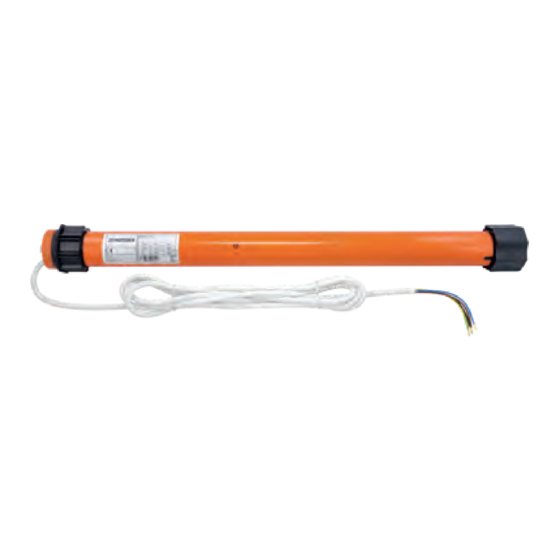
Shutter motor wiring:
6
Connect the roller shutter motor and switch (or timer) to the mains.
•
The electrical connection of the roller shutter motor and control unit may only be carried out by qualified personnel.
•
If the drive should run in the opposite direction after installation, the motor's upstream and downstream leads (brown + black) must be turned.
•
Power grid
230 V / 50 Hz
1) brown / black = L1 / Phase
2) blue = N Neutral conductor
3) green/yellow = PE Protective conductor
Adjustment cable ESKS
The connection diagram of time switches differs from this
circuit diagram! Please refer to the corresponding manual
for the connection diagram.
1 (L1)
2 (N)
3 (PE)
Wall bearing +
Ball bearing
1 (Up/Down)
2 (Up/Down)
3 (N)
4 (PE)
1) black = Departure or ascent
2) brown = Departure or ascent
3) blue = N Neutral conductor
4) green/yellow = PE Protective conductor
1 (Up/Down)
2 (Up/Down)
3 (N)
4 (PE)
If the end points are set using the ESKS adjustment cable, do
not connect the switch or timer until after the end positions
have been set (page 9)!
3T-MOTORS Tubular motors | Installation instructions
Shutter motor
230 V / 50 Hz
Shutter motor
230 V / 50 Hz
8