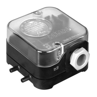
Dungs LGW A2P Series 작동 및 조립 지침 - 페이지 3
{카테고리_이름} Dungs LGW A2P Series에 대한 작동 및 조립 지침을 온라인으로 검색하거나 PDF를 다운로드하세요. Dungs LGW A2P Series 6 페이지. Air pressure switch, air pressure switch with test button
Dungs LGW A2P Series에 대해서도 마찬가지입니다: 작동 및 조립 지침 (8 페이지), 작동 및 조립 지침 (8 페이지), 사용 설명서 (12 페이지)

Gerät darf nicht als Hebel be-
nutzt werden
Do not use unit as lever.
Ne pas utiliser le pressostat
comme un levier.
L'apparecchio non deve
essere usato come leva.
Druckanschluß LGW...A2
Geeignete Schläuche (für Luft,
Rauch- und Abgase) einsetzen.
Schlauchinnendurchmesser A
max. 4 mm
Schlauchaußendurchmesser B
max. 15 mm
Schläuche gegen unbeabsichtig-
tes Abziehen sichern: Kabelbin-
der oder Schlauchschelle oder
Ω - Schelle.
A
B
Einbau
LGW...A2P
1. Der Druckwächter wird direkt auf
einen Rohrstutzen mit R 1/4
Außengewinde aufgeschraubt.
Bild 1.
2. Nach Einbau Dichtheits- und
Funktionskontrolle durchführen.
Auf vibrationsfreien Einbau
achten! Bild 2.
1
Nr. No. 14
Geeignetes
Dichtmittel
einsetzen!
Use proper seal-
ing compounds!
Utiliser une pâte à
joint adaptée!
Impiegare materia-
le di tenuta ade-
guato!
3 ... 6
M
max.
T
max.
M
max.
LGW...A2 pressure connection
Use suitable hoses (for air, flue and
exhaust gases)
Max. 4 mm inner hose diameter A
Max. 15 mm outer hose diameter B
Secure
hoses
to
prevent
unintentional removal: use cable
tie or cable clip or Ω clip.
–
Installation of
LGW...A2P
1. Screw the pressure switch di-
rectly on a tube socket with R 1/
4 outer thread (see Fig. 1).
2. After installation, perform a leak-
age and function test.
Ensure that the pressure
switch is installed free of
vibration (see Fig. 2).
Nr. No. 22
DN
6
Rp
1/8
M
25
max.
T
15
max.
Prise de pression LGW...A2
Utiliser les tubes appropriés (pour
l'air, la fumée et les gaz brûlés).
Diamètre intérieur du tube
max. 4 mm
Diamètre intérieur du tube
max. 15 mm
Faire le nécessaire afin que les
tubes ne puissent pas être enlevés
par inadvertance: fixation par at-
tache - collier ou clips Ω.
Made in Germany
Montage
LGW...A2P
1. Le pressostat peut se visser di-
rectement sur un piquage R 1/4"
Fig.1.
2. Après le montage contrôler la
jonction et l'étanchéité.
Veiller à ce que l'appareil
ne subisse pas de vibra-
tions ! Fig. 2.
2
8
1/4
≤
35
[Nm] t
10 s
≤
20
[Nm] t
10 s
Attacco di pressione LGW...A2
Per aria, gas di combustione e di
scarico, impiegare tubi flessibili
A
adeguati
Diametro interno del tubo A
B
max. 4 mm
Diametro esterno del tubo B
max. 15 mm
Assicurare i tubi contro il pericolo
di distacco involontario serven-
dosi di serratubi, fascette per
tubi o fascette a forma di Ω.
–
Made in Germany
Installazione
LGW...A2P
1. Il pressostato viene avvitato di-
rettamente su un tubo di soste-
gno con filetto esterno R 1/4
(Fig.1)
2. Dopo il montaggio effettuare i
controlli di tenuta e funzionalità.
Evitare possibilità di vibra-
zioni! Fig 2.
