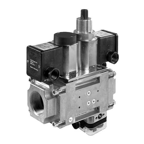
Dungs DMV-D/634 설치 지침 매뉴얼 - 페이지 7
{카테고리_이름} Dungs DMV-D/634에 대한 설치 지침 매뉴얼을 온라인으로 검색하거나 PDF를 다운로드하세요. Dungs DMV-D/634 9 페이지. Dual modular nema 4x safety shutoff valves with proof of closure

Proof of Closure
Location
The proof of closure switch is factory installed; it visually and
electrically indicates valve position. When the valve is closed
(NO position) an orange light is visible, when the valve is open
(NC position) a green light is visible.
Conduit Connection
• Before connecting conduit to the proof of closure switch,
position the proof of closure switch so that there is no torque
from the wiring or conduit. If the switch needs to be rotated,
loosen the slotted set screw on the side. The switch may
be removed from the brass adapter for wiring, however,
DO NOT turn the proof of closure switch after tightening
the slotted set screw.
• Tighten the slotted set screw so that the proof of closure
switch housing is secure. (16 lb-in torque)
Wiring
• Do not exceed the electrical ratings given in the proof of
closure switch specifications.
• Use 14 or 16 gauge wire for at least 75 ˚C (167 ˚F).
• Connect wire to the appropriate terminal of the proof of
closure switch (see the wiring diagram). COM to the L1,
Ground to ground, NO to the Proof of Closure terminal of
the Flame Safeguard and N to L2. The ORANGE light shall
be on when the valve is closed, the GREEN light shall be
on when the valve is open (FM requirement).
Annual Testing
All wiring must comply with local electrical
codes, ordiances and regulations.
L2
N
Do not wire the valve switch to close a circuit
that will directly power another safety shutoff
valve. Doing so could result in a safety valve being
energized and opened rather than remaining closed.
7 ... 9
1 Increment
2
Proof
Terminal
CPI 400
1
Made in Germany
Closed Position
Red Wire
Indicator
3
Yellow Wire
Orange
L1; COM
Green
Ground
• Perform a switch continuity test at least annually to verify
that the proof of closure switch is working properly.
• Make sure that there is no power to the proof of closure
switch.
• Shut the upstream ball valve to stop the flow of gas into the
valve train.
• With the valve de-energized, use a multimeter and verify
that there is continuity between the switch contacts 3 (COM)
and 2 (NO). Then verify that there is no continuity between
the switch contacts 3 (COM) and 1 (NC).
• Energize the valve that the proof of closure switch is mount-
ed to. Use a multimeter and verify that there is continuity
between the switch contacts 3 (COM) and 1 (NC). Then
verify that there is no continuity between the switch contacts
3 (COM) and 2 (NO).
• If you experience a problem, contact DUNGS.
• De-energize the valve and replace the cover on the proof
of closure switch.
• Open the upstream ball valve.
Proof of Closure Switch Specifications
Switch
SPDT
Switch Action
Valve open: Switch in NC position, Green light on.
Valve closed: Switch in NO position, Orange light on.
Contact Rating
10 A res, 8 FLA, 48 LRA @120 VAC
Enclosure
NEMA Type 4
Ambient/Fluid Temperature
-40 °F to 150 °F
L1
Proof of closure switch
Orange Lamp
(valve closed)
Com
3
Green Lamp
(valve opened)
L2 (N)
Flame Safeguard
Proof of Closure
2
terminal
N
1
